In Part 1, I talked at how a binaural recording is made, and I also mentioned that the spatial effects may or may not work well for you for a number of different reasons.
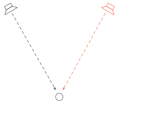
Let’s go back to the free field with a single “perfect” microphone to measure what’s happening, but this time, we’ll send sound out of two identical “perfect” loudspeakers. The distances from the loudspeakers to the microphone are identical. The only difference in this hypothetical world is that the two loudspeakers are in different positions (measuring as a rotational angle) as shown in Figure 1.
Figure 1: Two identical, “perfect” loudspeakers in a free field with a single “perfect” microphone.
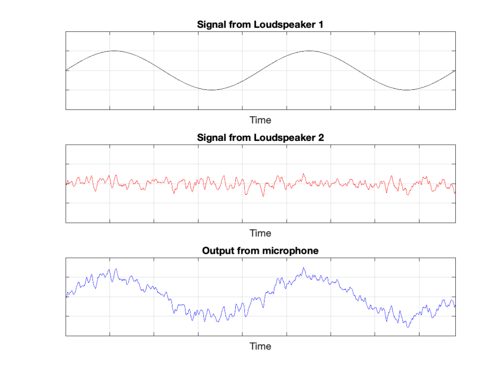
In this example, because everything is perfect, and the space is a free field, then output of the microphone will be the sum of the outputs of the two loudspeakers. (In the same way that if your dog and your cat are both asking for dinner simultaneously, you’ll hear dog+cat and have to decide which is more annoying and therefore gets fed first…)
Figure 2: The output from the microphone is the sum of the outputs from the two loudspeakers. At any moment in time, the value of the top plot + the value of the middle plot = the value of the bottom plot.
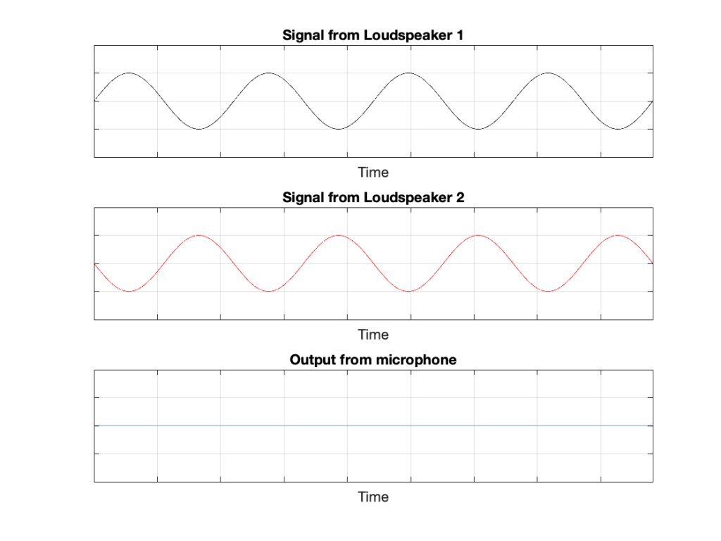
IF the system is perfect as I described above, then we can play some tricks that could be useful. For example, since the output of the microphone is the sum of the outputs of the two loudspeakers, what happens if the output of one loudspeaker is identical to the other loudspeaker, but reversed in polarity?
Figure 3: If the output of Loudspeaker 1 is exactly the same as the output of Loudspeaker 2 except for polarity, then the sum (the output of the microphone) is always 0.
In this example, we’re manipulating the signals so that, when they add together, you nothing at the output. This is because, at any moment in time, the value of Loudspeaker 2’s output is the value of Loudspeaker 1’s output * -1. So, in other words, we’re just subtracting the signal from itself at the microphone and we get something called “perfect cancellation” because the two signals cancel each other at all times.
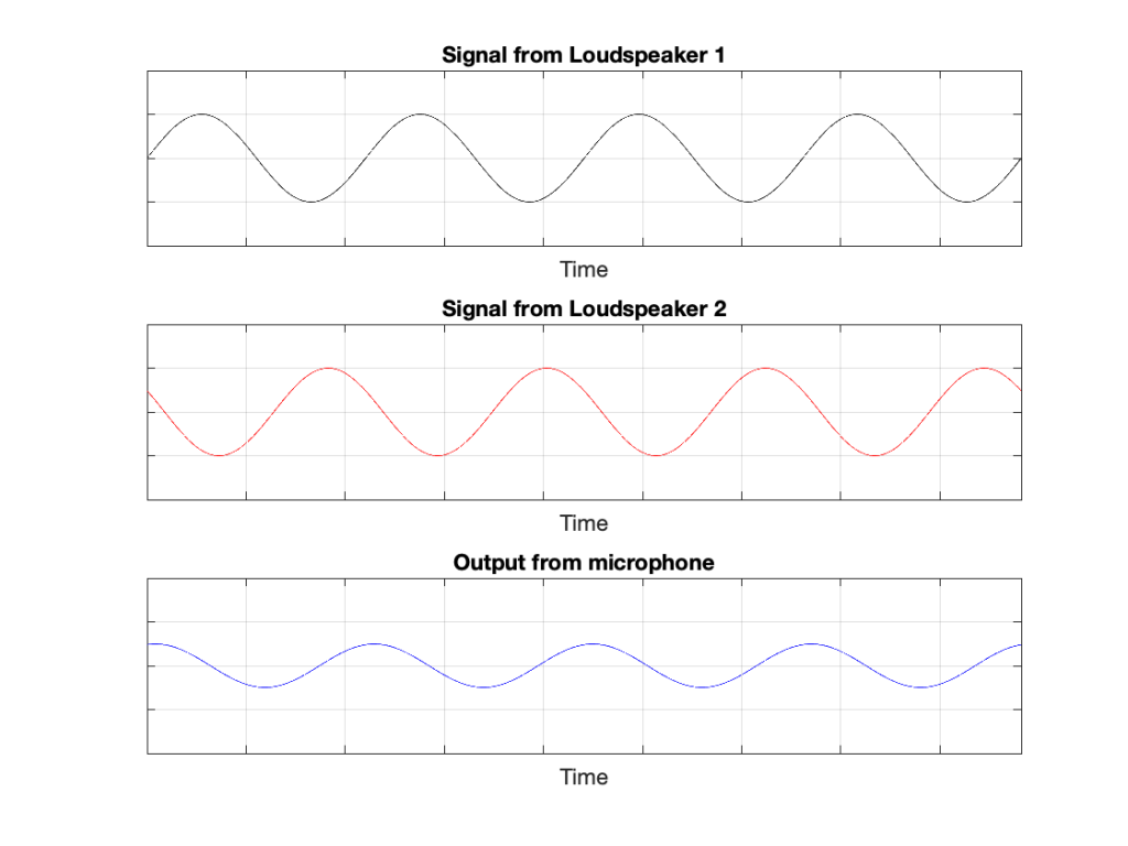
Of course, if anything changes, then this perfect cancellation won’t work. For example, if one of the loudspeakers moves a little farther away than the other, then the system is broken, as shown below.
Figure 4: A small shift in time in the output of Loudspeaker 2 cases the cancellation to stop working so well.
Again, everything that I’ve said above only works when everything is perfect, and the loudspeakers and the microphone are in a free field; so there are no reflections coming in and ruining everything.
We can now combine these two concepts:
using binaural signals to simulate a sound source in a location (although this would normally be done using playback over earphones to keep it simple) and
using signals from loudspeakers to cancel each other at some location in space as a
to create a system for making virtual loudspeakers.
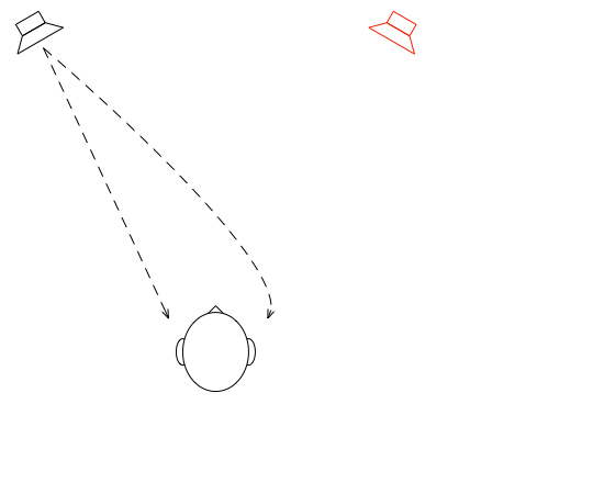
Let’s suspend our adherence to reality and continue with this hypothetical world where everything works as we want… We’ll replace the microphone with a person and consider what happens. To start, let’s just think about the output of the left loudspeaker.
Figure 5: The output of the left loudspeaker reaches both ears with different time/frequency characteristics caused by the HRTF associated with that sound source location.
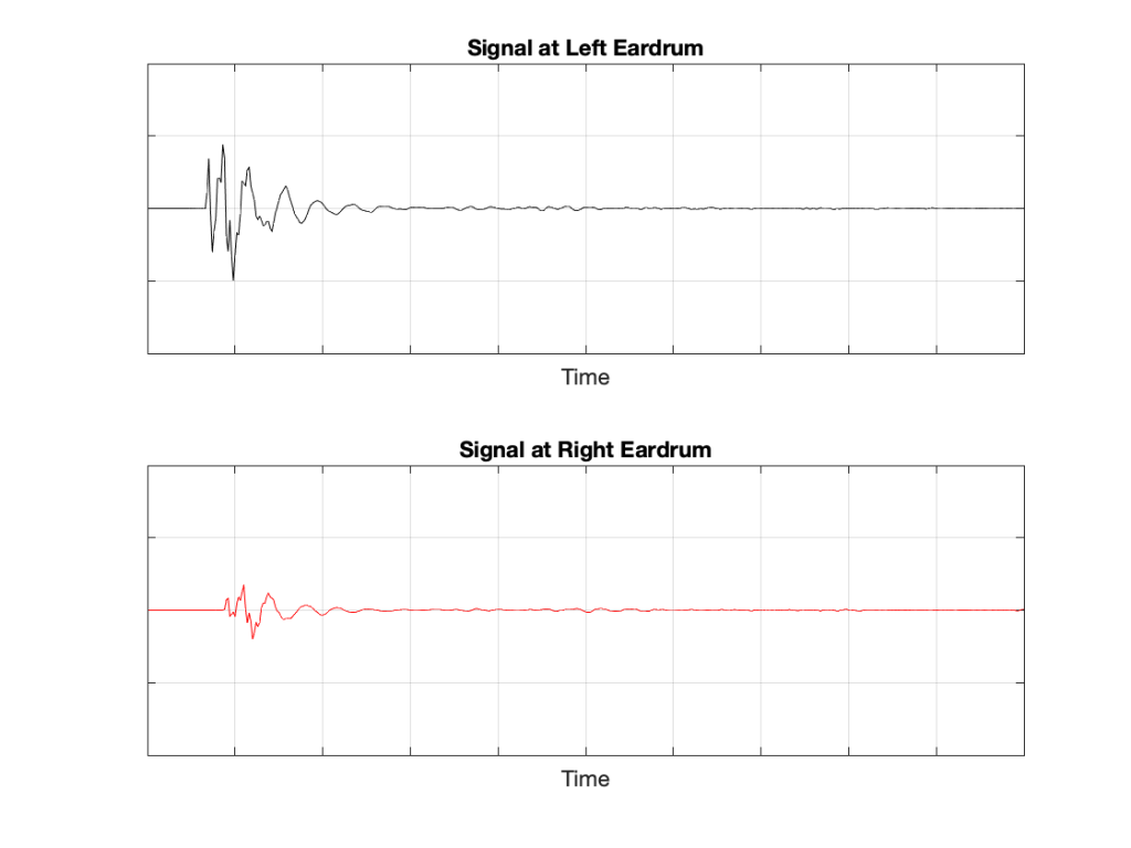
If we plot the impulse responses at the two ears (the “click” sound from the loudspeaker after it’s been modified by the HRTFs for that loudspeaker location), they’ll look like this:
Figure 6: The impulse responses of the HRTFs for a sound source at 30º left of centre.
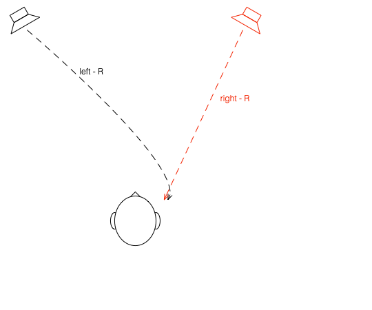
What if were were able to send a signal out of the right loudspeaker so that it cancels the signal from the left loudspeaker at the location of the right eardrum?
Figure 7: What if we could cancel the signal from the left loudspeaker at the right ear using the right loudspeaker?
Unfortunately, this is not quite as easy as it sounds, since the HRTF of the right loudspeaker at the right ear is also in the picture, so we have to be a bit clever about this.
So, in order for this to work we:
Send a signal out of the left loudspeaker. We know that this will get to the right eardrum after it’s been messed up by the HRTF. This is what we want to cancel…
…so we take that same signal, and
filter it with the inverse of the HRTF of the right loudspeaker (to undo the effects of the HRTF of the right loudspeaker’s signal at the right ear)
filter that with the HRTF of the left loudspeaker at the right ear (to match the filtering that’s done by your head and pinna)
multiply by -1 (so that it will cancel when everything comes together at your right eardrum)
and send it out the right loudspeaker.
Hypothetically, that signal (from the right loudspeaker) will reach your right eardrum at the same time as the unprocessed signal from the left loudspeaker and the two will cancel each other, just like the simple example shown in Figure 3. This effect is called crosstalk cancellation, because we use the signal from one loudspeaker to cancel the sound from the other loudspeaker that crosses to the wrong side of your head.
This then means that we have started to build a system where the output of the left loudspeaker is heard ONLY in your left ear. Of course, it’s not perfect because that cancellation signal that I sent out of the right loudspeaker gets to the left ear a little later, so we have to cancel the cancellation signal using the left loudspeaker, and back and forth forever.
If, at the same time, we’re doing the same thing for the other channel, then we’ve built a system where you have the left loudspeaker’s signal in the left ear and the right loudspeaker’s signal in the right ear; just like a pair of headphones!
However, if you get any of these elements wrong, the system will start to under-perform. For example, if the HRTFs that I use to predict your HRTFs are incorrect, then it won’t work as well. Or, if things aren’t time-aligned correctly (because you moved) then the cancellation won’t work.
Without connecting external loudspeakers, Bang & Olufsen’s Beosound Theatre has a total of 11 independent outputs, each of which can be assigned any Speaker Role (or input channel). Four of these are called “virtual” loudspeakers – but what does this mean? There’s a brief explanation of this concept in the Technical Sound Guide for the Theatre (you’ll find the link at the bottom of this page), which I’ve duplicated in a previous posting. However, let’s dig into this concept a little more deeply.
To begin, let’s put a “perfect” loudspeaker in a free field. This means that it’s in a space that has no surfaces to reflect the sound – so it’s an acoustic field where the sound wave is free to travel outwards forever without hitting anything (or at least appear as this is the case). We’ll also put a “perfect” microphone in the same space.
Figure 1: A loudspeaker and a microphone (the circle) in a free field: an infinite space completely free of reflective surfaces.
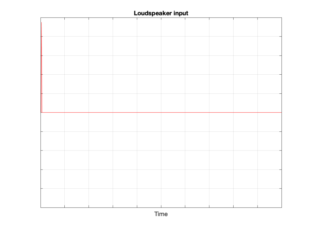
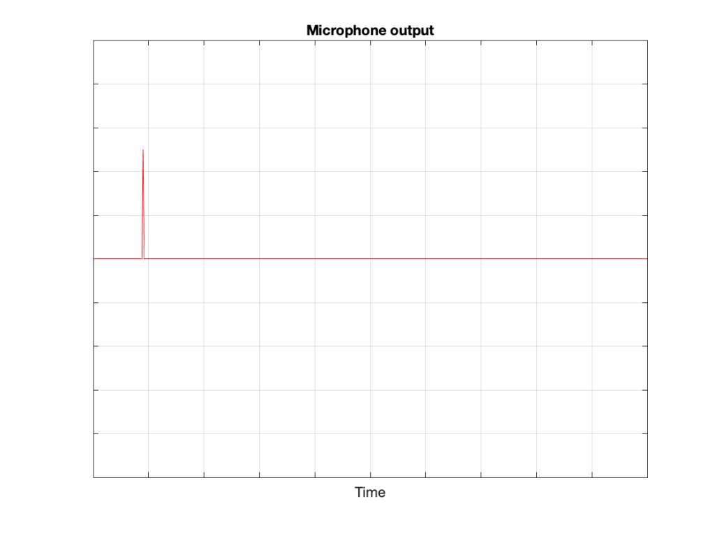
We then send an impulse; a very short, very loud “click” to the loudspeaker. (Actually a perfect impulse is infinitely short and infinitely loud, but this is not only inadvisable but impossible, and probably illegal.)
Figure 2: The “click” signal that’s sent to the input of the loudspeaker.
That sound radiates outwards through the free field and reaches the microphone which converts the acoustic signal back to an electrical one so we can look at it.
Figure 3: The “click” signal that is received at the microphone’s location and sent out as an electrical signal.
There are three things to notice when you compare Figure 3 to Figure 2:
The signal’s level is lower. This is because the microphone is some distance from the loudspeaker.
The signal is later. This is because the microphone is some distance from the loudspeaker and sound waves travel pretty slowly.
The general shape of the signals are identical. This is because I said that the loudspeaker and the microphone were both “perfect” and we’re in a space that is completely free of reflections.
What happens if we take away the microphone and put you in the same place instead?
Figure 4: The microphone has been replaced by something more familiar.
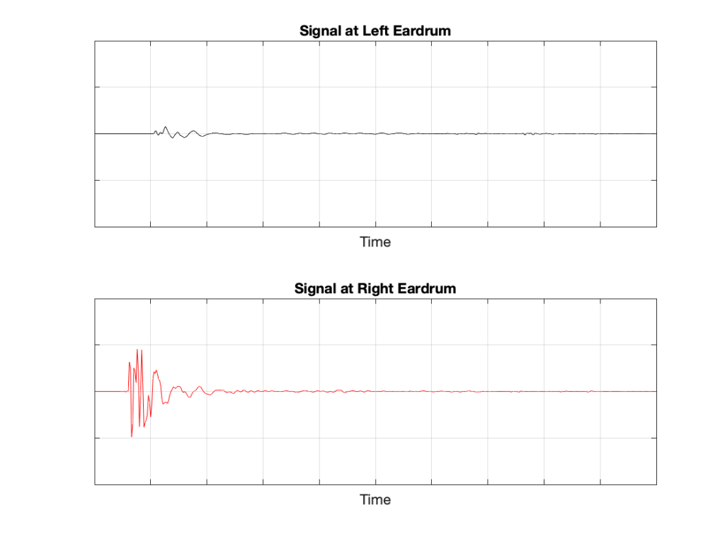
If we now send the same click to the loudspeaker and look at the “outputs” of your two eardrums (the signals that are sent to your brain), these will look something like this:
Figure 5: The outputs of your two eardrums with the same “click” signal from the loudspeaker.
These two signals are obviously very different from the one that the microphone “hears” which should not be a surprise: ears aren’t microphones. However, there are some specific things of which we should take note:
The output of the left eardrum is lower than that of the right eardrum. This is largely because of an effect called “head shadowing” which is exactly what it sounds like. The sound is quieter in your left ear because your head is in the way.
The signal at the right eardrum is earlier than at the left eardrum. This is because the left eardrum is not only farther away, but the sound has to go around your head to get there.
The signal at the right eardrum is earlier than the output of the microphone output (in Figure 3) because it’s closer to the loudspeaker. (I put the microphone at the location of the centre of the simulated head.) Similarly the left ear output is later because it’s farther away.
The signal at the right eardrum is full of spikes. This is mostly caused by reflections off the pinna (the flappy thing on the side of your head that you call your “ear”) that arrive at slightly different times, and all add together to make a mess.
The signal at the left eardrum is “smoother”. This is because the head itself acts as a filter reducing the levels of the high frequency content, which tends to make things less “spiky”.
Both signals last longer in time. This is the effect of the ear canal (the “hole” in the side of your head that you should NOT stick a pencil in) resonating like a little organ pipe.
The difference between the signals in Figures 2 and 4 is a measurement of the effect that your head (including your shoulders, ears/pinnae) has on the transfer of the sound from the loudspeaker to your eardrums. Consequently, we geeks call it a “head-related transfer function” or HRTF. I’ve plotted this HRTF as a measurement of an impulse in time – but I could have converted it to a frequency response instead (which would include the changes in magnitude and phase for different frequencies).
Here’s the cool thing: If I put a pair of headphones on you and played those two signals in Figure 5 to your two ears, you might be able to convince yourself that you hear the click coming from the same place as where that loudspeaker is located.
Although this sounds magical, don’t get too excited right away. Unfortunately, as with most things in life, reality tends to get in the way for a number of reasons:
Your head and ears aren’t the same shape as anyone else’s. Your brain has lived with your head and your ears for a long time, and it’s learned to correlate your HRTFs with the locations of sound sources. If I suddenly feed you a signal that uses my HRTFs, then this trick may or may not work, depending on how similar we are. This is just like borrowing someone else’s glasses. If you have roughly the same prescription, then you can see. However, if the prescriptions are very different, you’ll get a headache very quickly.
In reality, you’re always moving. So, even if the sound source is not moving, the specific details of the HRTFs are always changing (because the relative positions and angles to your ears are changing) but my system doesn’t know about this – so I’m simulating a system where the loudspeaker moves around you as you rotate your head. Since this never happens in real life, it tends to break the simulation.
The stuff I showed above doesn’t include reflections, which is how you determine distance to sources. If I wanted to include reflections, each reflection would have to have its own HRTF processing, depending on its angle relative to your head.
However, hypothetically, this can work, and lots of people have tried. The easiest way to do this is to not bother measuring anything. You just take a “dummy head” -a thing that is the same size as an average human head (maybe with an average torso) and average pinnae* – but with microphones where the eardrums are – and you plunk it down in a seat in a concert hall and record the outputs of the two “ears”. You then listen to this over earphones (we don’t use headphones because we want to remove your pinnae from the equation) and you get a “you are there” experience (assuming that the dummy head’s dimensions and shape are about the same as yours). This is what’s known as a binaural recording because it’s a recording that’s done with two ears (instead of two or more “simple” microphones).
If you want to experience this for yourself, plug a pair of headphones into your computer and do a search for the “Virtual Barber Shop” video. However, if you find that it doesn’t work for you, don’t be upset. It just means that you’re different: just like everyone else.* Typically, recordings like this have a strange effect of things sounding very close in the front, and farther away as sources go to the sides. (Personally, I typically don’t hear anything in the front. All of the sources sound like they’re sitting on the back of my neck and shoulders. This might be because I have a fat head (yes, yes… I know…) and small pinnae (yes, yes…. I know…) – or it might indicate some inherent paranoia of which I am not conscious.)
* Of course, depressingly typically, it goes without saying that the sizes and shapes of commercially-available dummy heads are based on averages of measurements of men only. Neither women nor children are interested in binaural recordings or have any relevance to such things, apparently…
If you you get an audiometry test done, you’ll be shown into a small room, about the size of a public bathroom stall. Someone will put a pair of headphones on you, and pass you a small handle with a button. Your instructions are to press the button if you hear a tone. Then the audiometrist will leave the room, closing the door, and you’ll suddenly realise that if there’s any noise in this room, it’s because you’re making it.
Then you hear a beep in your left ear. You press the button. You hear a quieter beep. Press. Quieter beep. Press…. …. …. Beep, press… …. …. …. Beep, press…. New frequency beep, loud again. Press… and so on.
What’s happening here is that you’re presented with a sine tone at some frequency, probably loud enough for you to hear. You press. The tone gets quieter, and you press again. Eventually, the tone is so quiet that you cannot hear it (this is normal) so you don’t press. So, the tone gets louder, and you press. Then it gets quieter again, until you can’t hear it again.
By crossing over that threshold of “can hear” and “can’t hear” a couple of times, the audiometrist finds out whether or not you got lucky… If you bottom out at the same level a couple of times in a row, then that’s your threshold of hearing at that frequency in that ear.
The frequency changes (usually by 1 octave, but sometimes less), and the whole process is repeated.
If you get a full test done, then this is probably done at 9 frequencies (250, 500, 1k, 1.5k, 2k, 3k, 4k, 6k, and 8kHz) in both ears individually – 18 tests in all.
You’ll then be given a sheet of paper, or at least shown a plot of your hearing threshold. Typically, if you have “normal” hearing (whatever that means) your thresholds will all be sitting on a horizontal line marked 0 dB. If you’re “better than normal” then you get a negative score, if you’re “worse than normal” you get a positive score.
What does this mean?
Let’s start over.
If a lot of people do this test, and we only test at 1 kHz, we’ll find out that, after the results are averaged, the group can hear the 1 kHz sine tone when the change in air pressure at the ear entrance is 20 µPa. We’re not going to talk about what this means other than to say that “sound is a change in air pressure over time, and that pressure is measured in pascals, abbreviated Pa”. Needless to say, 20 µPa is pretty quiet, since it’s the quietest sound a group of people can hear at 1 kHz when you take their average.
If you did that test at a much lower frequency, you would find out that people aren’t as good at hearing quiet sounds. In other words, at 100 Hz, the sine tone has to be louder than 20 µPa for people to hear it.
The same is true if you repeated the test at a much higher frequency – say, 10,000 Hz.
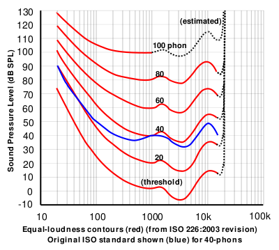
If you did this test at a lot of frequencies, then you’d find out that, on average, the threshold of hearing for a human follows the bottom red line of the plot in Figure 1, borrowed from Wikipedia.
Figure 1: The bottom red curve is the average threshold of hearing for a human being.
That bottom plot shows the threshold of hearing for different frequencies, plotted in dB SPL. Notice that, at 1 kHz, the line is at 0 dB SPL. This is because 0 dB SPL is defined to be the average threshold of hearing of a human at 1 kHz, which is 20 µPa. So, it’s not an accident…
Looking at that plot, you can see that, in order to hear a sine tone at 20 Hz, the tone has got to be more than 70 dB louder (that’s a LOT louder). So, a microphone “sees” a 73 dB SPL, 20 Hz sine tone as being louder than a 0 dB SPL, 1 kHz sine tone – but as far as you’re concerned, they’re both “the quietest sound you can hear” – therefore, they’re the same level.
If we take that threshold of hearing curve, and we play tones at those levels for those frequencies, then you should “just be able to” hear them. So, we’ll call those levels “0 dB” – since it’s the same as what is expected of you.
In other words, the piece of paper you got from the audiometrist tells you how much above or below that red threshold of hearing YOU sit.
Now, let’s back up a bit.
I said that, in your test, you only went up to 8 kHz. This is because, above that (and possibly even before that) the headphones might not be trust-worthy, and even a tiny movement (say a couple of millimetres) in the position of the headphones will have a (relatively) big effect on the level at your eardrum. So, rather than get people worried about losing their hearing at 20,000 Hz (when, in fact, they were actually just wearing the headphones 1 mm too far forward), you won’t get tested.
Notice how variable that threshold of hearing line is. There are big changes in level over the “audible” frequency range.
Remember that the threshold of hearing curve is an AVERAGE of a lot of people. Just like no one has 2.6 children, no one has this exact response. And, if you are some freak of nature and you DO have exactly that response, you don’t for long… we all get old…
Notice how that threshold of hearing curve only goes up to about 16 kHz, and above that it says “estimated”. See point #1.
Now, you should know that your ability to hear a sine tone at some frequency is defined as how your ability compares to an expectation based on an average, within a relatively small frequency band: 250 to 8 kHz.
Then you look at a textbook or you read a website that says “humans can hear from 20 Hz to 20 kHz”, which is not enough information to be either true or false… It’s like saying “humans are usually between 0 and 10 m tall” which is also sort of true, but also adequately vague to be potentially worse-than-useless information.
The truth is, unfortunately, much more complicated… However, it’s fair to say that, in order for you to just hear a sine tone at 20 kHz, it would have to be much, much louder than one at 1 kHz. In fact, if I played a 20 kHz sine tone loud enough for you to hear, measured that level, and then played a 1 kHz sine tone for you at the same level, you’d probably punch me – after you had passed out due to the pain, woken up, hunted me down, and found me… (I’d already have run away by then….)
So what?
We humans like nice, tidy, answers. “It will rain tomorrow” is preferable to “there is a 70 – 80% chance of scattered showers in the afternoon tomorrow”. We even get mad when the information is correct, but we interpret it tidily… For example, we’ll complain about getting rained on in the middle of our hike, when there was only a 10% chance of rain. On the other hand, if there was a 10% chance of winning 1 Million dollars in the lottery, we’d all buy a ticket.
Anyways, once-upon-a-time, when the committee for inventing the compact disc was holding meetings, they said “what should the sampling rate be?” and someone said “at least 40 kHz, because we can hear up to 20 kHz”. (The reason it’s 44100 is related to the fact that the bits were stored as black and white stripes on video tape, and NTSC and PAL come close to meeting each other close to that number, when you look at the numbers of lines per field and frames per second.)
Of course, like any first-generation thing, digital recording equipment wasn’t very good at the start (back around 1980 or so) – so the first DDD recordings that were released on CD sounded… well…. weird. There was quantisation distortion because they hadn’t figured out dither yet, only 12 or 13 of the bit values were working properly on the ADC’s, the anti-aliasing filters were implemented as analogue circuits, so they let some stuff through that aliased, and they rang (“sang along”) with the signal at a high frequency… All of that added up to “weird” – possibly even “bad”. Then, people who had good equipment (high-end turntables or, even better, 1/4″ tape running at 30 ips) listened to this new format, decided it was bad, and that was that.
Some of them asked “why is is bad?” and one answer they came up with was the band limiting… If the system can’t capture or store or play materials above 20 kHz, then it’s useless… Right? Maybe…
Then, instruments were put in front of measurement microphones and spectra were measured – and the proof was in. Trumpets with harmon (wah-wah) mutes, when pointing directly at the microphone, contain harmonics as high as 50 kHz! This must explain why CDs sound bad! Right? Maybe…
Then Rupert Neve did a demo at an AES (Audio Engineering Society) convention where he played people two tones. Both were at 7 kHz, but one was a sine wave and the other was a square wave (at some level). The question was: have a listen and tell me which is which. The results were the same as if everyone was just guessing. (Remember that, in order to make a square wave, you need to add odd harmonics – so the lowest-frequency content difference between a 7 kHz sine wave and a 7 kHz square wave is at 21 kHz.) Proof that we don’t need to go above 20 kHz, right? Maybe…
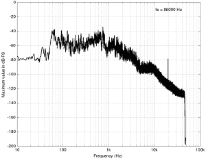
Some years ago, I took some “high resolution” audio files and measured their spectral content. One particularly interesting result is shown in Figures 2, below.
Figure 2: The spectral content of a 96/24 “high resolution” audio file I bought.
Look at that spike in the top end – around 20 kHz. What musical instrument makes that sound? The answer is “no musical instrument makes that sound – at least none of the baroque instruments in that recording make that sound. As I wrote back in 2014:
If you’re wondering what it might be, I asked a bunch of smart friends, and the best explanation we can come up with is that it’s noise from a switched-mode power supply that is somehow bleeding into the recording. HOW it’s bleeding into the recording is a potentially interesting question for recording engineers. One possibility is that one of the musicians was charging up a phone in the room where the microphones were – and the mic’s just picked up the noise. Another possibility is that the power supply noise is bleeding electrically into the recording chain – maybe it’s a computer power supply or the sound card and the manufacturer hasn’t thought about isolating this high frequency noise from the audio path. Or, maybe it’s something else.
Interestingly, this is a conflict of two engineers. The designer of the power supply (assuming that’s what it is…) said “I’ll put the switching frequency above 20 kHz so that no one will hear it” and the recording engineer said “I’ll record this at 96 kHz so that people can get the content they’re missing…” The problem is that the content you’re missing is something you don’t want…
Similarly, if you listen to Eric Clapton’s “Unplugged” album with headphones or loudspeakers that have a low-enough low-frequency range, you’ll hear a loud thump, thump, thump going along with the music. This is the sound of someone tapping their foot on a temporary stage floor, shaking a vocal microphone. In my not-very-humble opinion, that should never have made it out to the public release. However, my guess is that the speakers it was mastered on didn’t go low enough… (OR, it was an artistic decision, and I would have done it differently.) Assuming that I’m right, then this is a second example where a “better” system sounds “worse”.
Of course, through all of this, I have assumed that your loudspeakers or headphones can produce the signals that we’re talking about in the direction that you’re sitting in, and that those signals are not being masked by other sounds in the room (like phone chargers singing…) However, to complicate things with reality would just be too far to go today…
Conclusions?
I don’t have any, but I have some questions and (as usual) some opinions…
Does a harmon mute on a trumpet produce energy at 50 kHz, if you’re sitting right in front of it? Yes.
Do you want to sit right in front of a trumpet with a harmon mute? Debatable.
Can a high-res audio recording include the sound of a phone charger? Yes.
Do you want to have an expensive recording of a baroque ensemble with obligato phone charger? Probably not – the charger is not in Buxtehude’s original score as far as I can see.
Can you hear the difference between a 7 kHz sine and a 7 kHz square wave? Depends on the speaker / headphone, the listening position, the background noise level, and whether or not you were out clubbing last night. Heads or tails?
Will you feel better by knowing that your file contains “audio” content above 20 kHz? Probably. Placebos have been known to work bigger miracles than this. (But don’t forget the stuff I said about sampling rate converters earlier…)
“Love at first sight? Let me just put on my glasses.” Ljupka Cvetanova, The New Land
When I’m working on the sound design for a new pair of (over-ear, closed) headphones, I have to take off my glasses (which makes it difficult for me to see my computer screen…) I’ll explain.
Let’s over-simplify and consider a block diagram of a closed (and therefore “over-ear”) headphone, sitting on one side of your head. This is represented by Figure 1.
Fig 1. A simplified diagram of an over-ear headphone with a sealed cabinet, sitting correctly on the side of your head.
One of the important things to note there is that the air in the chamber between the headphone diaphragm and the ear canal is sealed from the outside world.
So, if I put such a headphone on an artificial ear (which is a microphone in a small hole in the middle of a plate – it is remarkably well-represented by the red lines in Figure 1….) I can measure its magnitude response. I’ll call this the “reference”. It doesn’t matter to me what the measurement looks like, since this is just a magnitude response which is the combination of the headphone’s response and the artificial ear’s response – with some incorrect positioning thrown into the mix.
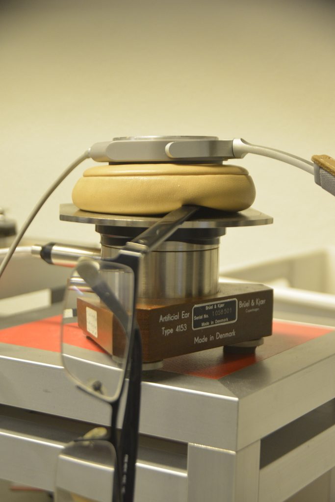
Fig 2. The headphones in question, placed on an Artificial Ear for the first measurement.
If I then remove the headphones from the plate, and put them back on, in what I think is the same position, and then do the measurement again, I’ll get another curve.
Then, I’ll subtract the “reference measurement” (the first one) from the second measurement to see what the difference is. An example of this is plotted in Figure 2.
Fig 3. The difference between a magnitude response measurement and the reference measurement of the same ear cup on the same headphones, 1/6th octave smoothed. As you can see, it’s slightly different – but not much. I was VERY careful about re-positioning the headphones on the plate.
Now, let’s consider what happens when the seal is broken. I’ll stick a small piece of metal (actually an Allan key, or a hex wrench, depending on where you live) in between the headphones and the plate, causing a leak in the air between the internal cavity and the outside world, as shown in Figure 4.
Fig 4. A small piece of metal that lifts the leather of the ear cup and causes a small leak around it.
Fig 5. A simplified diagram of an over-ear headphone with a sealed cabinet, sitting incorrectly on the side of your head.
We then repeat the measurement, and subtract the original Reference measurement to see what happened. This is shown in Figure 6.
Fig 6. The magnitude response difference caused by a small leak in the chamber.
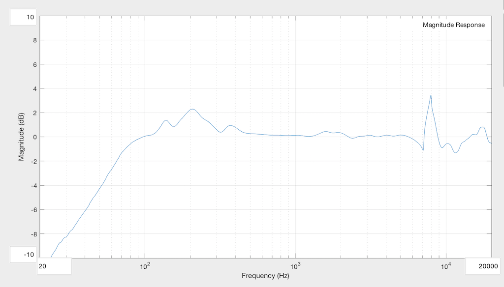
As you can see, the leak in the system causes us to lose bass, primarily. In the very low end, the loss is significant – more than 10 dB down at 20 Hz! Basically, what we’ve done here is to create an acoustical high-pass filter. (I’m not going to go into the physics of why this happens… That’s too much information for this posting.) You can also see that there’s a bump around 200 Hz which is also a result of the leak. The sharp peak up at 8 kHz is not caused by the leak – it’s just an artefact of the headphones having moved a little on the plate when I put in the Allen Key.
Now let’s make the leak bigger. I’ll stick the arm of my glasses in between the plate and the leather pad.
Fig 7. The arm of my glasses, stuck in the system to make the leak worse…
The result of this measurement (again with the Reference subtracted) is shown in Figure 8.
Fig 8. The magnitude response difference caused by a bigger leak in the chamber.
Now you can see that the high pass filter’s cutoff frequency has risen, and the resonance in the system has not only increased in frequency (to 400 Hz or so) but also in magnitude (to almost +10 dB! Again, the sharp wiggles at the top are mostly just artefacts caused by changes in position…
Just to check and see that I haven’t done something stupid, I’ll remove the glasses, and run the measurement again…
Fig 9. Back to the original – just as a sanity check
The result of this measurement is shown in Figure 10.
Fig 10. Back to a system without leaks… and a magnitude response that closely matches the original – at least in the low end…
So, there are a couple of things to be learned here…
Firstly, if you and a friend both listen to the same pair of closed, sealed headphones, and you disagree about the relative level of bass, check that you’re both not wearing glasses or large earrings…
The more general interpretation of that previous point is that small leaks in the system have a big effect on the response of the headphones in the low-frequency region. Those leaks can happen as a result of many things – not just the arm of your glasses. Hair can also cause the problem. Or, for example, if the headphones are slightly big, and/or your head is slightly small, then the area where your jaw meets your neck under your pinna (around your mastoid gland) is one possile place for leaks. This can also happen if you have a very sharp corner around your jaw (say you are Audrey Hepburn, for example), and the ear cup padding is stiff. Interestingly, as time passes, the foam and covering soften and may change shape slightly to seal these leaks. So, as the headphones match the shape of your head over time, you might get a better seal and a change in the bass level. This might be interpreted by some people as having “broken in” the headphones – but what you’ve actually done is to “break in” the padding so that it fits your head better.
Secondly, those big, sharp spikes up the high end aren’t insignificant… They’re the result of small movements in the headphones on the measuring system. A similar thing happens when you move headphones on your head – but it can be even more significant due to effects caused by your pinna. This is why, many people, when doing headphone measurements, will do many measurements (say, 5 to 10) and average the results. Those errors in placement are not just the result of shifts on the plate – they may also be caused by differences in “clamping pressure” – so, if I angled the headphones a little on that table, then they might be pressing harder on the artificial ear, possibly only on one side of the ear cup, and this will also change the measured response in the high frequency bands.
Fig 11. My glasses on a B&K HATS used for measurements instead of the artificial ear. Check out that leak… This is similar to the problem that I have when I wear glasses when listening to the same headphones.
Of course, it’s possible to reduce this problem by making the foam more compliant (a fancy word for “squishy”) – which may, in turn, mean that the response will be more different for different users due to different head widths. Or the problem could be reduced by increasing the clamping force, which will in turn make the headphones uncomfortable because they’re squeezing your head. Or, you could embrace the leak, and make a pair of open headphones – but those will not give you much passive noise isolation from the outside world. In fact, you won’t have any at all…
So as you can see, as a manufacturer, this issue has to be balanced with other issues when designing the headphones in the first place…
Or you can just take off your glasses, close your eyes, and listen…
Addendum
Please don’t jump too far in your conclusions as a result of seeing these measurements. You should NOT interpret them to mean that, if you wear glasses, you will get a 10 dB bump at 400 Hz. The actual response that you will get from your headphones depends on the size of the leak, the volume of the chamber in the ear cup (which is partly dependent on the size of your pinna, since that occupies a significant portion of the volume inside the chamber) and other factors.
The take-home message here is: when you’re evaluating a pair of closed, over-ear headphones: small leaks have an effect on the low frequency response, and small changes in position have an effect on the high-frequency response. The details of those effects are almost impossible to predict accurately.