I’ve started working with a number of my colleagues on a series of videos for internal training at Bang & Olufsen. They were kind enough to make some of these videos publicly available.
This video illustrates the difference between the two main categories of reflections.
I’ve started working with a number of my colleagues on a series of videos for internal training at Bang & Olufsen. They were kind enough to make some of these videos publicly available.
This video demonstrates some of the individual components of a room’s acoustical contributions.
I’ve started working with a number of my colleagues on a series of videos for internal training at Bang & Olufsen. They were kind enough to make some of these videos publicly available.
This video demonstrates one of the more important problems that we face in dealing with a room’s acoustical contribution to “the sound” of a loudspeaker: room modes (or room resonances), as well as some basic introduction to some strategies for compensating for them.
I’ve started working with a number of my colleagues on a series of videos for internal training at Bang & Olufsen. They were kind enough to make some of these videos publicly available.
This video presents an intuitive explanation of why we typically need bigger loudspeaker drivers to reproduce low frequency bands, and smaller drivers for higher bands.
I’ve started working with a number of my colleagues on a series of videos for internal training at Bang & Olufsen. They were kind enough to make some of these videos publicly available.
This video explains why loudspeaker drivers are typically put in enclosures (boxes), the three types of enclosures that we use (sealed, ported, and passive radiators), and the differences in impact that these enclosure types have on the loudspeaker’s behaviour.
I’ve started working with a number of my colleagues on a series of videos for internal training at Bang & Olufsen. They were kind enough to make some of these videos publicly available.
This video explains the various components inside a typical loudspeaker driver.
I’ve started working with a number of my colleagues on a series of videos for internal training at Bang & Olufsen. They were kind enough to make some of these videos publicly available.
This one explains why loudspeaker drivers produce a narrower “beam” of sound at higher frequencies and how multiple loudspeaker drivers can be used to control both the direction and the width of an acoustic beam.
I’ve started working with a number of my colleagues on a series of videos for internal training at Bang & Olufsen. They were kind enough to make some of these videos publicly available.
This video explains (and demonstrates) how recording engineers are able to control the perceived location of different sound sources in a two-channel stereo recording using different techniques.
I’ve started working with a number of my colleagues on a series of videos for internal training at Bang & Olufsen. They were kind enough to make some of these videos publicly available.
This video explains how we are able to localise the direction of and the distance to a sound source in the real world.
Note that there are two small errors in the video. I said that 800 µsec is 8 millionths of a second. It’s 800 millionths of a second. I’ll let you find the other error.
I’ve started working with a number of my colleagues on a series of videos for internal training at Bang & Olufsen. They were kind enough to make some of these videos publicly available.
This one explains some basic concepts of human hearing in the frequency domain, including how our hearing changes with level, the reason we use “loudness” processing in loudspeakers, and psychoacoustic masking.
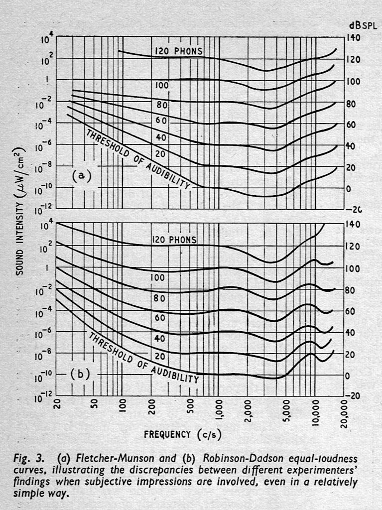
In case you’re interested in looking into this a little further, the curves I show there are from the Robinson-Dadson experiments, not the Fletcher-Munson version. An interesting place to start learning about the history of this is the March, 1962 issue of Wireless World magazine, which includes this plot comparing the two.