If you’ve read the three introductory parts of this series, linked above; and if you’re still awake, then we are ready to start putting things together and jumping to incorrect conclusions…
Let’s say that you’ve been hired to specify a digital audio system for some reason (we’ll assume that it’s an LPCM system – nothing exotic). Using the information I’ve told you so far, you can make two decisions in your specification:
You select a bit depth to be enough to give you the dynamic range you desire. In this case, “dynamic range” means the “distance” in level between the loudest sound you can record / store / transmit (I isn’t say what the “digital audio system” was going to be used for) and the inherent noise floor of the system. If you’re recording the background noise on an airplane while it’s in flight, you don’t need a big dynamic range, because it’s always loud, and never changes. However, if you’re recording a Japanese Taiko Drummer group, you’ll need a huge usable dynamic range because the loud parts of the performance are a LOT louder than the quietest parts.
As we saw in Part 3, an LPCM digital audio system cannot record any audio that has a frequency higher than 1/2 the sampling rate. So, you select a sampling rate that is at least 2x the highest frequency you’re interested in. For example, if you believe the books that say you can hear from 20 Hz to 20,000 Hz, then you might decide that your sampling rate has to be at least 40,000 Hz. On the other hand, if you’re making a subwoofer that you know will never be fed a signal above 120 Hz, then you don’t need a sampling rate higher than 240 Hz.
Don’t get angry yet. I’m just keeping these numbers simple to make the math easy. Later on, I’ll explain why what I just said might not be correct.
Mistake #1
I just jumped to at least three conclusions (probably more) that are going to haunt me.
The first was that my “digital audio system” was something like the following:
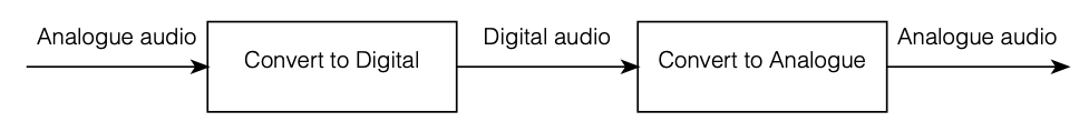
As you can see there, I took an analogue audio signal, converted it to digital, and then converted it back to analogue. Maybe I transmitted it or stored it in the part that says “digital audio”.
However, the important, and very probably incorrect assumption here is that I did nothing to the signal. No volume control, no bass and treble adjustments… nothing.
Mistake #2
We assumed above that we can define the system’s dynamic range based on the dynamic range of the audio signal itself. However, this makes the assumption that the noise floor of the digital system and the noise floor of your audio signal are identical, which is probably not true. As we saw in Part 2, the noise generated by TPDF dither is white – it has the same probability of having a given amount of energy per Hertz. Since we hear sound logarithmically (meaning that, to us, octaves are equal widths. Equal spacings in Hz are not.) This means that the noise sound “bright” to us – because there’s just as much energy in the top octave (say, 10 kHz to 20 kHz, if you believe the books) as there is in all other frequencies combined from 0 Hz up to 10 kHz.
If, however, the noise floor in your concert hall where the taiko drummers are playing is caused by the air conditioning system, then this noise will be a lot louder in the low frequencies than the the highs – which is not the same.
Therefore it’s too simplistic to say “the noise floor of the digital system” and the “noise floor of the signal” – since these two noise floors are different. (As Steven Wright said: “It doesn’t matter what temperature the room is, it’s always room temperature.”)
Mistake #3
As we’ll see later, if you’re going to do anything to the signal while it’s in the “digital domain”, then you need to take that into consideration when you’re deciding on your sampling rate. It’s not enough to say “useful audio bandwidth times 2” because there are some side effects that need to be remembered…
However, counter-intuitively, it could be that, in order to improve your system, you’ll want to make the sampling rate LOWER instead of HIGHER – so this is not a simple case of “more is better”.
We’ll get to that topic later. For now, I’ll leave you in suspense.
Some details
One thing we saw in Part 3 was that, if we have an audio signal with energy at a frequency higher than 1/2 the sampling rate, and if that signal gets into the analogue-to-digital converter (ADC), then the output of the ADC will contain an error. We’ll get out energy at frequencies that were not in the original, due to the effect called “aliasing“.
Once that’s in the digital audio signal, there’s no removing it, so we need to make sure that the too-high-frequency signals don’t get into the ADC’s input in the first place. This is done using a low-pass filter that (in theory) removes all energy in the signal above the Nyquist frequency (which is equal to 1/2 the sampling rate). Since that low-pass filter prevents aliasing, we call it an anti-aliasing filter. Normally, these days, that antialiasing filter is built into the ADC itself.
As we also saw in Part 3, the digital-to-analogue converter (DAC) has to smooth out the digital signal to convert it from a “staircase” wave to a smoother one. That’s also done with a low-pass filter that eliminates all the harmonics that would be required to make the staircase have sharp corners. Since this is done to re-construct the analogue signal, it’s called a “reconstruction filter“.
This means that, if we pull apart some of the components in the signal chain I showed in Figure 1, it really looks more like this:
