#3 in a series of articles about the technology behind Bang & Olufsen loudspeakers
I recently saw a posting on a website showing a “naked” BeoLab 18 – meaning one without the front grille. The enthusiasm generated by that photo made me think that there might be some interest is seeing some Bang & Olufsen loudspeakers when they’re really naked. Visitors to the acoustics department in Struer are greeted by a collection of loudspeakers that have been opened up for viewing. I’ll show some photos of these in future posts. Today, I’ll reveal just two loudspeakers – the BeoLab 3 and the BeoLab 11. Do not try this at home.
BeoLab 3
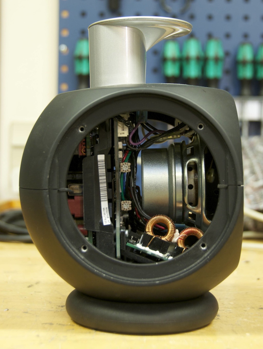
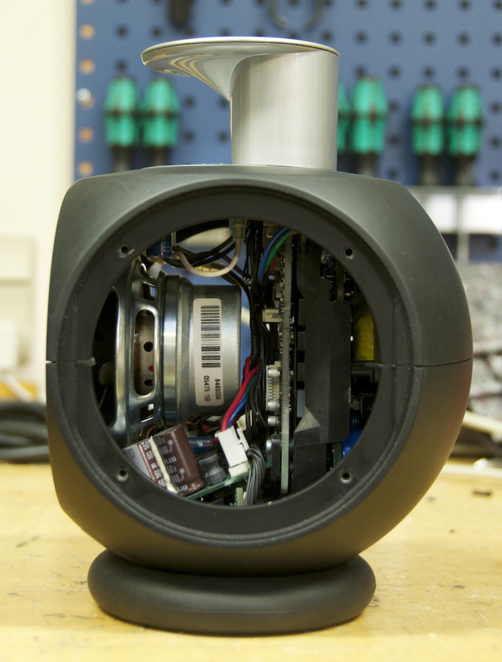
The BeoLab 3 is a two-way fully active loudspeaker with analogue filtering. It has ABL, two 125 W ICEpower Class-D amplifiers driving a 3/4″ tweeter and a 4″ woofer in the front. In addition, it has two side-mounted 4″ passive radiators. If you take the front woofer off, you’ll get a look inside it as is shown below.
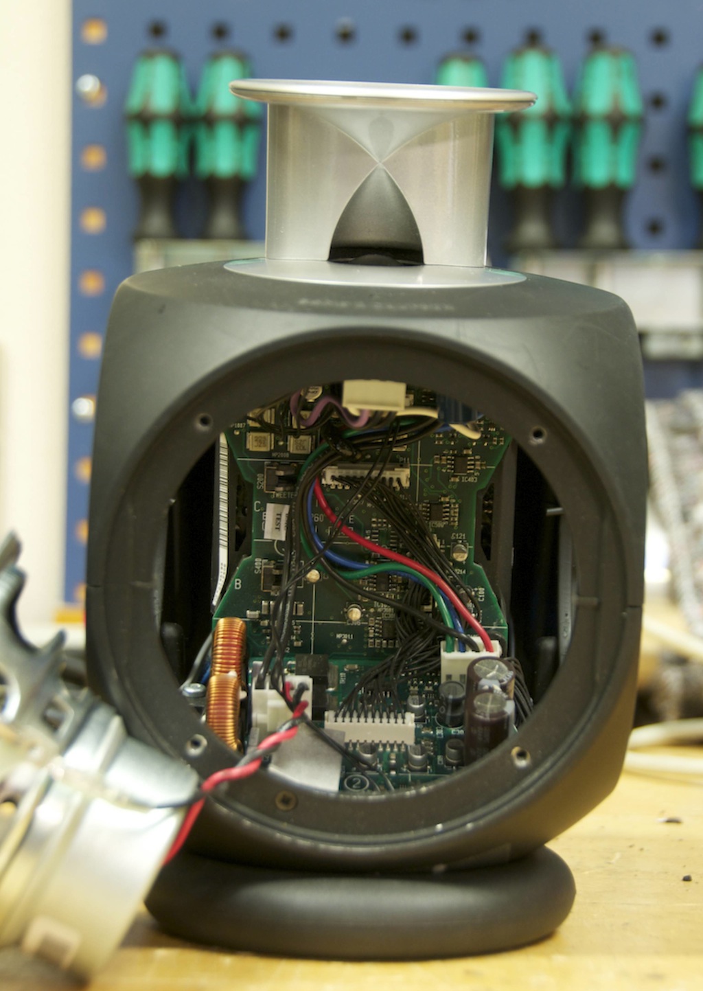
This gives you a direct view of the printed circuit board (PCB) with the analogue filtering and ABL circuitry which live directly behind and below the woofer.
In addition, you can see the PCB with the two power amplifiers on it.
Looking from the sides, through the holes the passive radiators normally occupy, you’ll see how little space there is behind the woofer when it’s mounted in the enclosure.
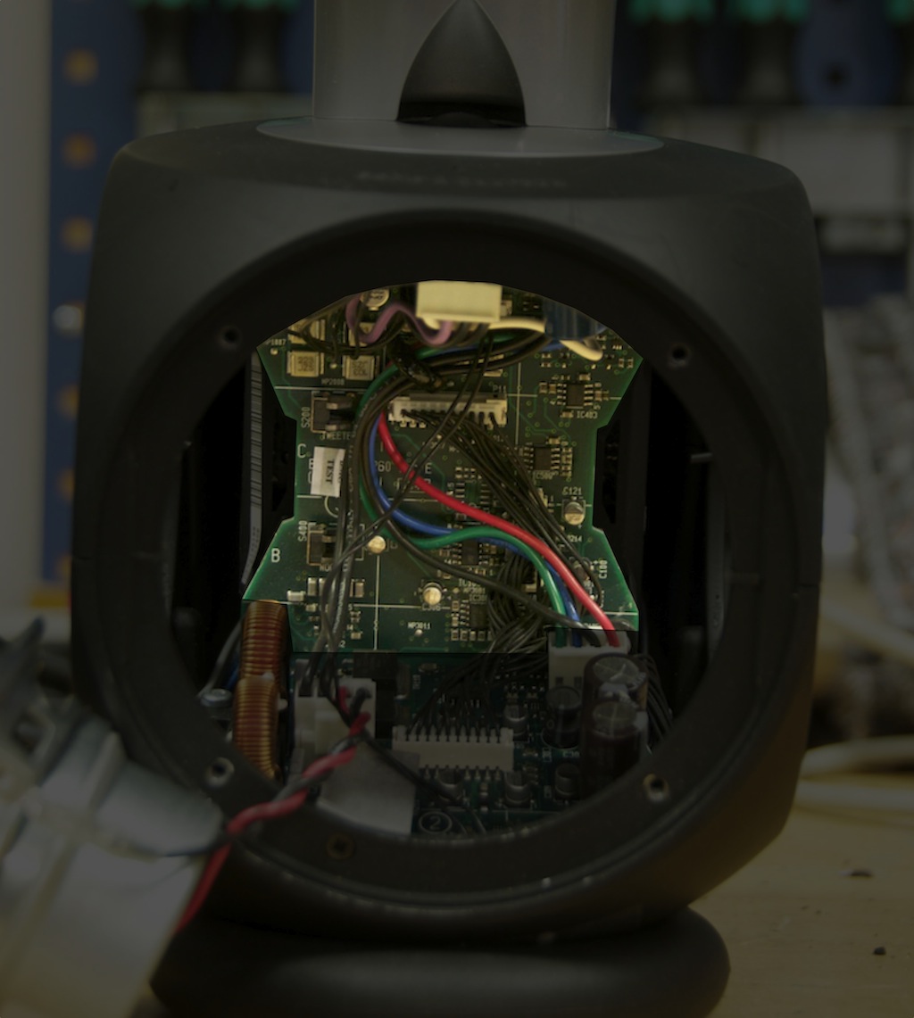
In the photo above, you can see two “potentiometers”, directly behind the woofer, attached to the vertical PCB that contains the filter circuitry (they have numbers printed on them and they look like the heads of phillips screws). These are for making gain adjustments to on the production line (or if you have to get your loudspeaker repaired) to ensure that the woofer and tweeter have the appropriate levels so that they not only match each other, but that they match the “golden sample” that we keep as a Master Reference. These are necessary to adjust for small differences in components within the circuitry as well as the exact sensitivities of the woofer and tweeter.
On the production line, this procedure is actually pretty cool. The acoustic response of the loudspeaker gets measured on the production line, then the two potentiometers are adjusted by hand to ensure that the response of the loudspeaker is correct – then the loudspeaker is measured again to make sure that the adjustment was performed correctly. This is done for each and every BeoLab 3 that we make.
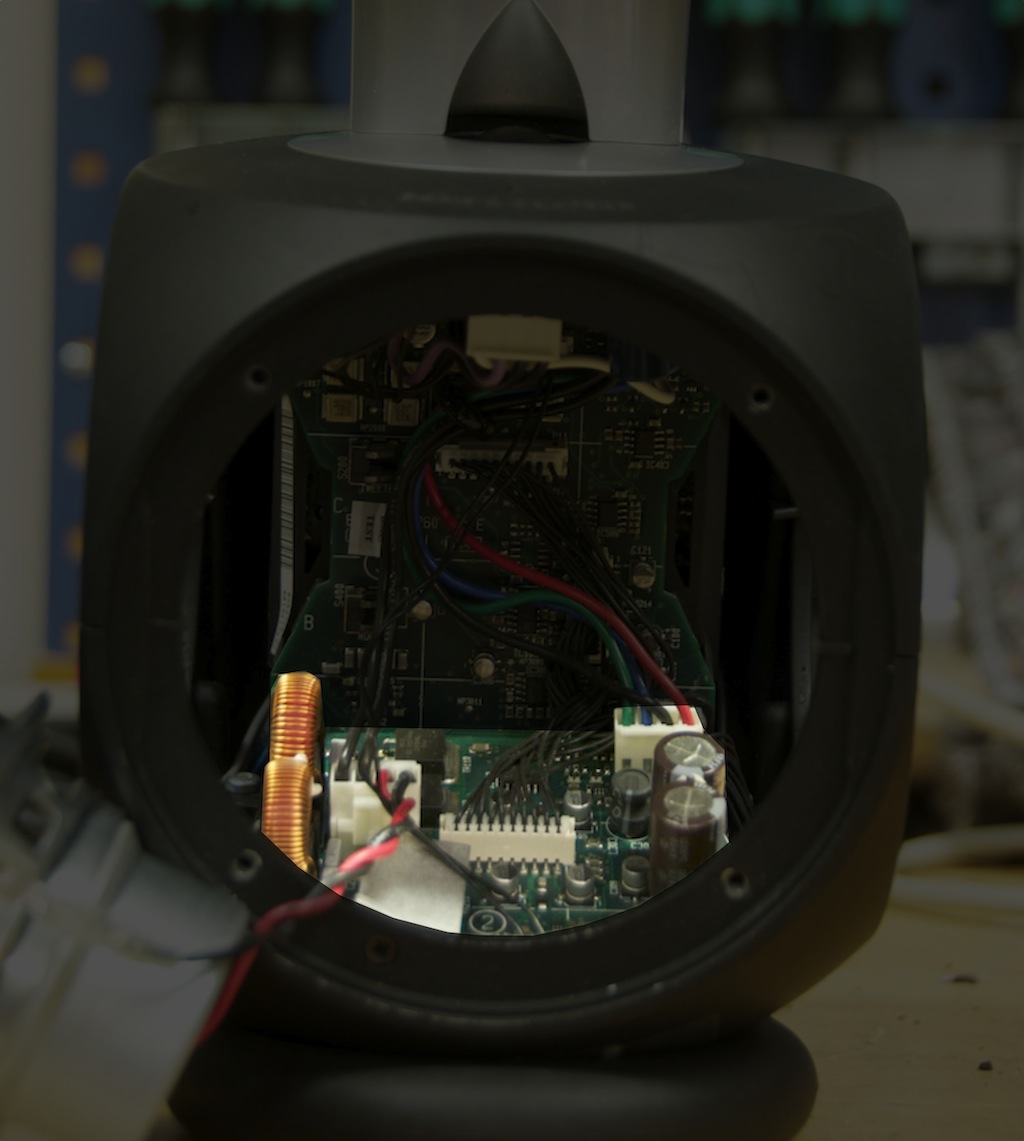
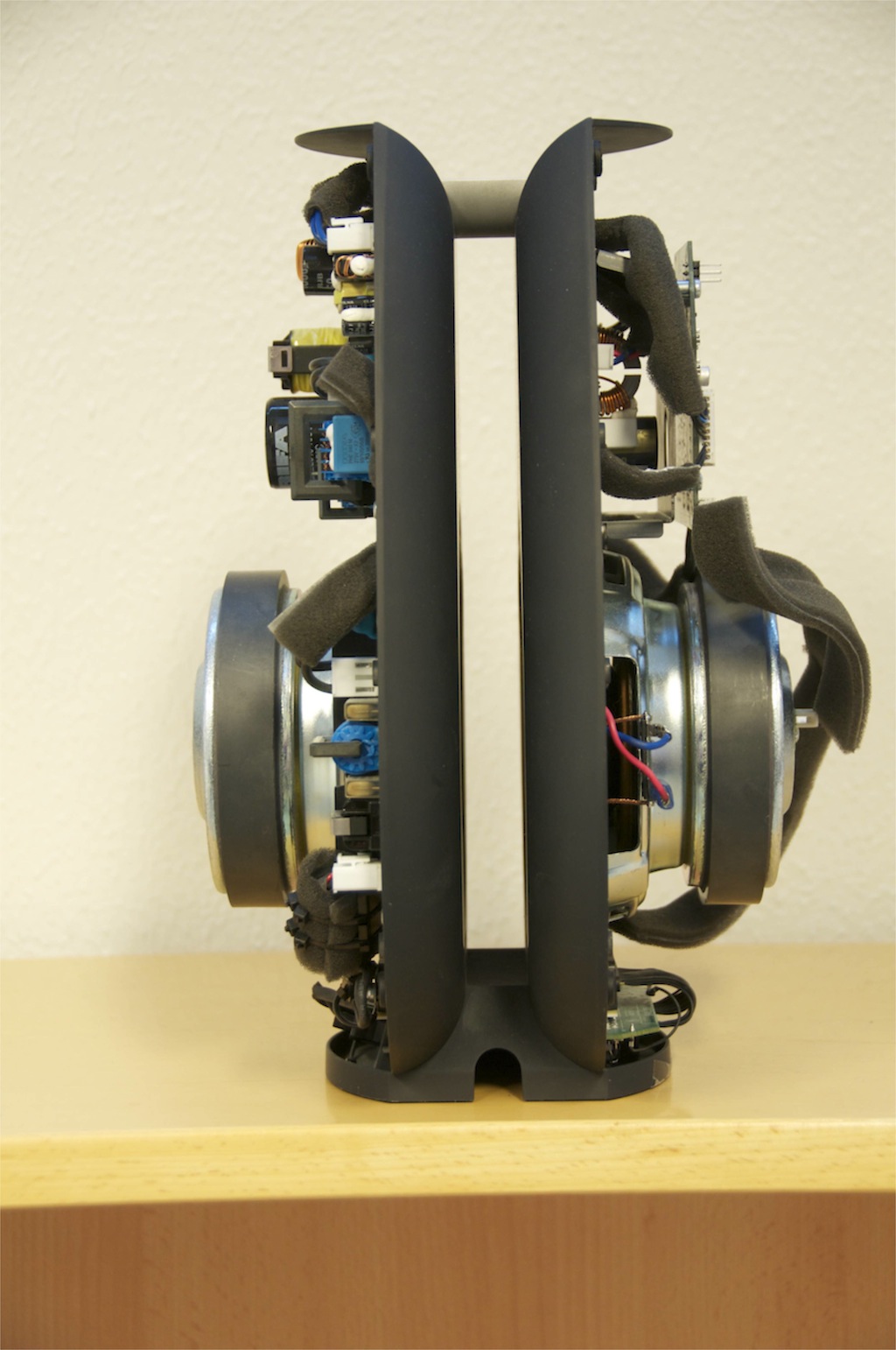
Note that the PCB containing the power supply which delivers the voltage rails and current to the entire loudspeaker is on the “back” of the enclosure, behind the PCB containing the filters and ABL. The photo below shows a highlight of that circuit – although it’s hard to see from the side.

I know it’s difficult to see everything in there, so let’s take a different look at the components. The photos below show what could be considered to be an “exploded view” of the BeoLab 3. This was done for a special exhibit, so don’t ask for a similar photo of other loudspeakers in the portfolio. Sorry.


BeoLab 11
A block diagram of the BeoLab 11 would be surprisingly similar to the BeoLab 3. It has two 200W ICEpower Class-D amplifiers for the two 6.5″ loudspeaker drivers (each in its own sealed enclosure), filtering (although this time, the filter circuit includes a bass management system that also has a high pass filter for a pair of external loudspeakers), ABL, and a power supply.

In the posting describing ABL, I mentioned that there are thermal sensors distributed inside B&O loudspeakers to allow the device to continually “know” how hot it is. The photo below shows one of those sensors. It’s mounted on the small, green PCB that is screwed directly to the magnet assembly of the woofer (in the centre of the silver circle). This tells the circuitry the temperature of the woofer magnet. By itself, this information is not really useful, since the woofer magnet can get very hot without suffering damage. What we’re REALLY worried about is the temperature of the wire voice coil that is located inside the magnet – however, we cannot mount a temperature sensor on the coil, since this would stop the loudspeaker from working properly. So, the loudspeaker’s circuitry contains a “thermal model” of the woofer which calculates the temperature of the voice coil based on the temperature of the woofer magnet and the amount of power that has been sent into the woofer. This allows the loudspeaker to calculate the temperature of the voice coil based on the magnet temperature and the music that you’re playing.

You may notice that there is no thermal sensor on the opposite woofer. This is because the same signal is being sent to both woofers, so it is safe to assume that the two magnets (and therefore the two voice coils) are the same temperature.

That’s it for this week. Next week, I’ll walk through our development process – describing the steps that we take when we develop a loudspeaker starting with the first meetings with the designer, all the way through to the first products off the production line.
alenvprekrsku says:
Thanks Geoff.
My B&O blog:
http://www.myaudioshop.si/forum_slo/posti/high_end/bangolufsen_od_iskre_do_ikone/page/
mark says:
Thank you.
I really appreciate your photos and explanation.
Sincerely,
Mark
Ingo says:
Hallo Tonmeister Geoff
Ich wollte mal schreibe das ich die Beolab 18 nun fast
ein Jahr an der Wand schweben habe.
Der Klang ist super abgestimmt. Manchmal ist der Sound erschreckend realistisch. Etwas mehr Details höre ich nur noch mit meinem In-Ohr-Monitor raus.
Ziemlich gelungen ist das Raumverhalten. Fast egal wo ich in meinem Wohnzimmer hocke, Klang gut und Stereo vorhanden.
Wer behauptet das die Teile keinen Bass können, Ich finde schon das es ordentlich ist.
Im Heimkino ohne Woofer wird es ein bisschen “dünn”.
Der Beolab 19 wäre natürlich ein Kraftpartner…
Aber auch ohne Subwoofer ist der Sound ausreichend,
wenn man in Nachbarfreundlichem Pegeln hört reicht es immer.
Ich gebe Ihnen mal 8,5 von 10 für den Klang.
Wenn man das Teil als Gesamtwerk betrachtet.
Klang, Design, Technik … 9,5 von 10!
Die Beolab 18 ist Ihnen tonal sehr gelungen.
Ich geniesse jeden Tag Musik damit.
Mit freundlichem Gruss
Ingo Essler
geoff says:
Hi Ingo,
Many thanks for your kind words. It’s great to hear that you’re still happy with your loudspeakers after a year of living with them! A great way to start the weekend… :-)
Thanks again!
-geoff
Florent Gatin says:
Hi Geoff,
Is there a specific material used by Bang & Olufsen to ensure airthightness when screwing the ‘lids’ on the Beolab 11? It looks like there is a grey-ish material in the grooves of the main housing.
Thank you!
geoff says:
Hi,
For the BeoLab 11, it’s a continuous foam rubber gasket that you see in the groove surrounding the cabinet.
In addition to this, the wires that run through to the opposite side of the loudspeaker (at the bottom of the device) go through rubber gasket/grommet. This not only ensures that the path for the wires is airtight, but that the wires do not vibrate and hit something and cause Rub and Buzz problems when playing loudly.
Note that, for other loudspeakers, the solution will be different, although the problem is the same…
Cheers
-geoff