I’ve started working with a number of my colleagues on a series of videos for internal training at Bang & Olufsen. They were kind enough to make some of these videos publicly available.
This one explains why loudspeaker drivers produce a narrower “beam” of sound at higher frequencies and how multiple loudspeaker drivers can be used to control both the direction and the width of an acoustic beam.
I’ve started working with a number of my colleagues on a series of videos for internal training at Bang & Olufsen. They were kind enough to make some of these videos publicly available.
This video explains (and demonstrates) how recording engineers are able to control the perceived location of different sound sources in a two-channel stereo recording using different techniques.
I’ve started working with a number of my colleagues on a series of videos for internal training at Bang & Olufsen. They were kind enough to make some of these videos publicly available.
This video explains how we are able to localise the direction of and the distance to a sound source in the real world.
Note that there are two small errors in the video. I said that 800 µsec is 8 millionths of a second. It’s 800 millionths of a second. I’ll let you find the other error.
I’ve started working with a number of my colleagues on a series of videos for internal training at Bang & Olufsen. They were kind enough to make some of these videos publicly available.
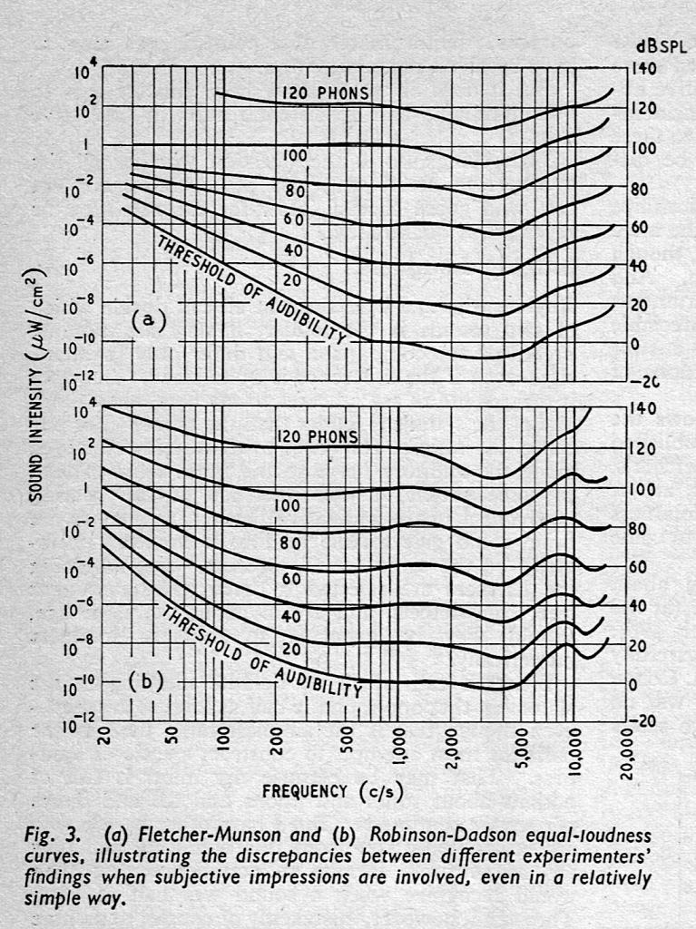
This one explains some basic concepts of human hearing in the frequency domain, including how our hearing changes with level, the reason we use “loudness” processing in loudspeakers, and psychoacoustic masking.
In case you’re interested in looking into this a little further, the curves I show there are from the Robinson-Dadson experiments, not the Fletcher-Munson version. An interesting place to start learning about the history of this is the March, 1962 issue of Wireless World magazine, which includes this plot comparing the two.
I’ve started working with a number of my colleagues on a series of videos for internal training at Bang & Olufsen. They were kind enough to make some of these videos publicly available.
This one is an explanation of the relationship between the frequency and the time domains, and why we often do “impulse response” measurements.
I’ve started working with a number of my colleagues on a series of videos for internal training at Bang & Olufsen. They were kind enough to make some of these videos publicly available.
This first one explains the basics: how sound is produced, how it travels through air, and some of its basic measures like the speeds of sound, frequency, wavelength, amplitude, and why sound gets quieter with distance.
This posting is just wrapping up the series. No more plots… I promise.
Of course, this entire series has focused the “greatest hits” of the crossover club which is a limited number of crossover types. There are many other options that I haven’t talked about, but my point was not to explain how to choose and design a crossover for a loudspeaker for the DIY’er. It was to
give a primer on some of the things to consider when implementing a crossover
instil instinctive suspicion and doubt when you read an advertisement (or a comment on the Internet) that says something like “this loudspeaker is good (or bad) because it has THIS kind of crossover.”
There are plenty of things that I didn’t (and won’t) talk about, such as:
Crossovers for loudspeakers with more than two outputs
Other crossover designs. For example, as a start, search for:
Malcom Hawksford Asymmetrical Crossover
Malcom Hawksford discussion of stochastic crossovers associated with DMLs
On thing that I intentionally avoided was crossover designs that use filters with extremely high orders, sometimes called “brick wall” crossovers. On paper, they avoid the possible issues with a signal in a given frequency band coming from two sources (e.g. a woofer and a tweeter), so if you ONLY consider them from this perspective, they’re a good idea. However, in my opinion, this is outweighed by the facts that you will probably get a discontinuity in the power response (unless the two drivers have identical three-dimensional radiation patterns at the crossover frequency) AND you will probably have a complete mess in the time domain. Bonkers-order filters aren’t free. (If you clicked on the link to Linkwitz’s page, above and just taken a quick glance, then you’ve probably read the statement at the top of the page that says “The sum of acoustic lowpass and highpass outputs must have allpass behavior without high Q peaks in the group delay.” One way to look at the group delay of a filter is to look at the slope of the phase response. If you make a crossover with really high-order filters, then one of the artefacts will be a high slope in the phase response around the crossover frequency.)
One other thing that I have not mentioned is the incorrect naming that is often associated with crossovers and filters in general. Many people say “FIR Filter” (Finite Impulse Response) when they actually mean “Linear phase filter”. It’s important to remember that you can’t have a linear phase filter without an FIR filter implementation, but certainly not all FIR filters are linear phase. (Weirdly, a linear phase filter does, in fact, have an infinite impulse response, both forwards and backwards in time… But that’s a description of the filter’s response and not how it would be implemented in a DSP-based signal flow.) This incorrect usage drives me nuts. (Then again, many things like this do. For example, I get annoyed when HR people draw a triangle on a whiteboard and call it a pyramid. You never know what’s going to set me off on a pedantic rant about nomenclature.)
The other thing that I didn’t talk about was another way to look at a Butterworth two-way crossover, in which you see it as lacking a component in the s-domain (using Laplace analysis), which is the reason its sum has an allpass characteristic. If you add the missing component (for example, using a third loudspeaker driver), then the allpass behaviour disappears. This is the concept behind Bang & OIufsen’s “Uni-phase” series of loudspeakers in the 1970s and 1980s. If you want to learn more about this, I’ve already written about it here, and Erik Bækgaard’s original paper from 1977 describing the idea more fully can be found here.
Finally, hopefully, you won’t come away from all of this with a conclusion that one crossover is the winner. A crossover is just one component in a long series- and parallel-chain of components that make up a loudspeaker. Changing any of the other components may require making a different decision about another. And, in order to make that decision, you can’t just consider the on-axis response (unless you live alone in an anechoic chamber (or outdoors…). You also need to think about things like
the off-axis responses
the power response
the phase response
the time response and maybe also
the implications on latency
your required signal processing power (e.g. in MIPS)
maybe some other stuff if you have checked all those boxes.
On the other hand, after all this, you should also know that you can’t just implement a crossover ignoring everything else in the chain, and think that it’ll just work. It won’t.
Part 14 showed the power responses of a theoretical loudspeaker made with two point-sources using a linear-phase crossover using the method that I explained in Part 7.
In Part 11, I showed the power responses when the loudspeaker is made with real drivers in a real enclosure.
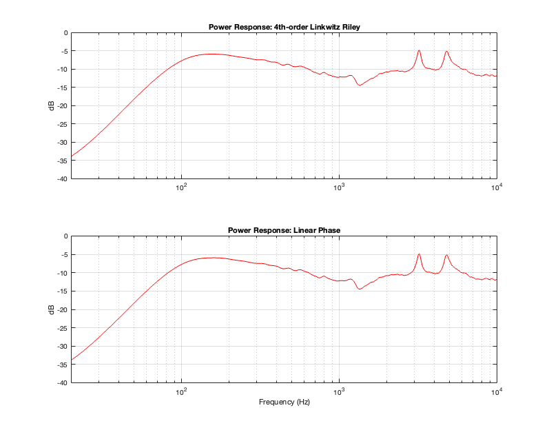
This posting shows the same as Part 11, except that I’ve implemented the crossover (at 1 kHz) using linear phase filters (again, with a really long window to avoid any discussion) instead of minimum phase filters.
Figure 15.1
Figure 15.1 shows the real-world power responses of an actual two-way loudspeaker using two crossover strategies. (The top plot was already shown in Part 11.)
Based on the conclusions from Part 14, it should not come as a surprise that a linear phase crossover will result in the same power response as a 4th-order Linkwitz Riley crossover. The only reason I’m showing this here is to prove that the earlier conclusion based on a theoretical simulation holds true in real life.
One important conclusion to make at this point is to realise that a loudspeaker that is implemented with a 4th-order Linkwitz Riley crossover and the same loudspeaker implemented with a linear phase crossover will have identical magnitude responses (in any direction – not just on-axis) and identical power responses. However, they will have different phase responses (in any chosen direction) and different temporal responses (aka impulse responses).
In Part 7, I showed the power responses of three loudspeakers made with point-source (and therefore perfectly omnidirectional at all frequencies, which also means that they have the same response in all direction) drivers.
In that posting, I calculated the power response for a loudspeaker made of two loudspeaker drivers, floating in space, with the assumption that both drivers are point-sources, and that they do not live in an enclosure that has any acoustical effects. I also calculated the responses for 3 different distances between the drivers, which were chosen as a function of the crossover frequency’s wavelength.
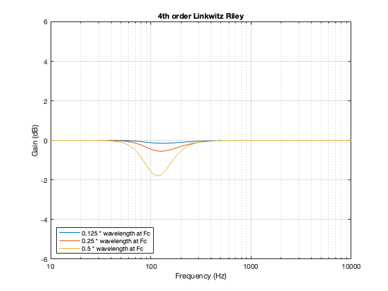
One of the crossover types whose power responses that I showed was the 4th-order Linkwitz Riley. The plots that I showed back then for that crossover type is reproduced here in Figure 14.1.
Figure 14.1: Power responses for a 2-way theoretical loudspeaker for three different distances between the drivers.
As I said, the details of how I calculated these power responses is detailed in Part 7.
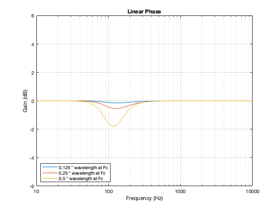
I calculated the power responses for a similar loudspeaker, using a linear phase crossover (with a really long window to avoid any discussion about this…) and with the same crossover frequency of 100 Hz and the same distances between the “drivers”. These power responses are shown below in Figure 14.2.
Figure 14.2: Power responses for a 2-way theoretical loudspeaker for three different distances between the drivers.
If you look at Figures 14.1 and 14.2 you could be forgiven for thinking that they look VERY similar. In fact, they’re essentially identical. This is because the 0º difference in phase caused by the linear phase crossover is the same as a 360º difference in phase caused by the 4th order Linkwitz Riley.
In other words, the message of this posting is that the power responses of a loudspeaker that has been implemented with a 4th order Linkwitz Riley crossover and the same loudspeaker with a linear phase crossover will have the same power responses, assuming that all other aspects of the loudspeaker are the same.
In the previous posting, I showed the frequency responses and impulse responses of the outputs of a crossover based on a linear phase filter strategy. One thing that can be seen in the impulse response plots in Figure 12.5 is that it never reaches a value of 0. It rings both backwards and forwards in time forever. However, this is not practical, since we don’t want to wait until the end of time to hear the output of our loudspeaker.
So, normally, we have to make a pragmatic choice about how long we’re willing to wait for the crossover filter’s to deliver an output. There are various ways to make this decision, but ultimately, we’re trying to balance the “error” in the responses of the crossover’s outputs with how long an input/output latency we’re willing to put up with. (We might also need to think about computational issues like how many calculations have to be done when you use a REALLY long filter, but I’m going to pretend that this is not an issue for this posting.)
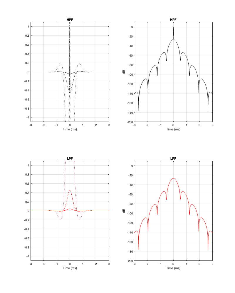
Figure 13.1. The left hand plots show the impulse responses of the two crossover outputs on three different scales: x1 (solid line), x10 (dash-dot line), and x100 (dotted line). The right-hand plots show the same impulse responses expressed in decibels.
It’s difficult to see from a linear plot of the impulse responses of the two filters, but the peak is in the middle, at Time = 0 ms. Extending outwards, both backwards and forwards in time, the impulse responses oscillates back and forth across the 0-amplitude line. This oscillation is easier to see when it’s plotted in decibels, but then you can’t see whether the linear value is positive or negative. So, it helps to look at both to get an idea of what’s happening.
One thing that might not be immediately obvious is that, apart from the big spike at Time = 0 ms on the high-pass filter response, the outputs of the two filters are identical in amplitude, but opposite in polarity. In other words, they are symmetrical. This makes sense when you consider that, by adding them together, the total result is a single spike at Time = 0 and an amplitude of 0 at all other times. In other other words, the outputs of the two filters “cancel each other out” at all times except Time = 0.
This is a little weird if you think of it as the tweeter cancelling the woofer – but you consider that it’s doing it in time, at very low levels, then it might make more intuitive sense.
What happens if you don’t want to wait too long to get the output? In other words, if we shorten the impulse response around the central spike? This is a technique that is called “windowing” where you slice a window of time out of the middle of the impulse response and use only that.
There are a number of ways to do this. We could just say “everything up to 1 ms before the spike and everything after 1 ms after the spike, we just convert to silence”. This is the simplest way to do it, but it’s also the dumbest.
A smarter way is to look at the impulse response shown above, and fade into the spike and then fade back out again. Then you just decide on the shape of the fade and its length. It could be a straight line, or it could be something fancy.
I’ve written a lot about windowing in another posting a long time ago. If you want to learn about this topic, you could start there, or any book or website that talks about time-domain processing and analysis of audio signals. I won’t explain windowing in this posting. It’ll just get too long…
For all of the analyses below I did the following:
Choose a crossover frequency
Implement the crossover using linear phase filters
Decide on a threshold in level (in dB below the spike at the input) to find out how long a window in time I’m going to use
Apply a Hann window to the filters’ impulse responses with the length that I found above
Show the magnitude and phase responses of the individual outputs as well as the summed total
Another way to do this would be to just decide on the length of the windowing (and find out the threshold of the level, below which you’re cutting the signal) and see what happens. Either way, you get a deviation in the response, you’re just setting a different parameter.
Fc = 1 kHz
Let’s start with a crossover frequency of 1 kHz. If I say that I want to extend the impulse response very far down in level, I’ll wind up getting a very accurate filter response (in other words, I’ll get what I expect), but it’ll have a long input/output latency (which is half of the total windowing time).
Figure 13.2. Fc = 1 kHz. Threshold = -250 dB Minimum Latency = 5.44 ms
Figure 13.3. Fc = 1 kHz. Threshold = -250 dB
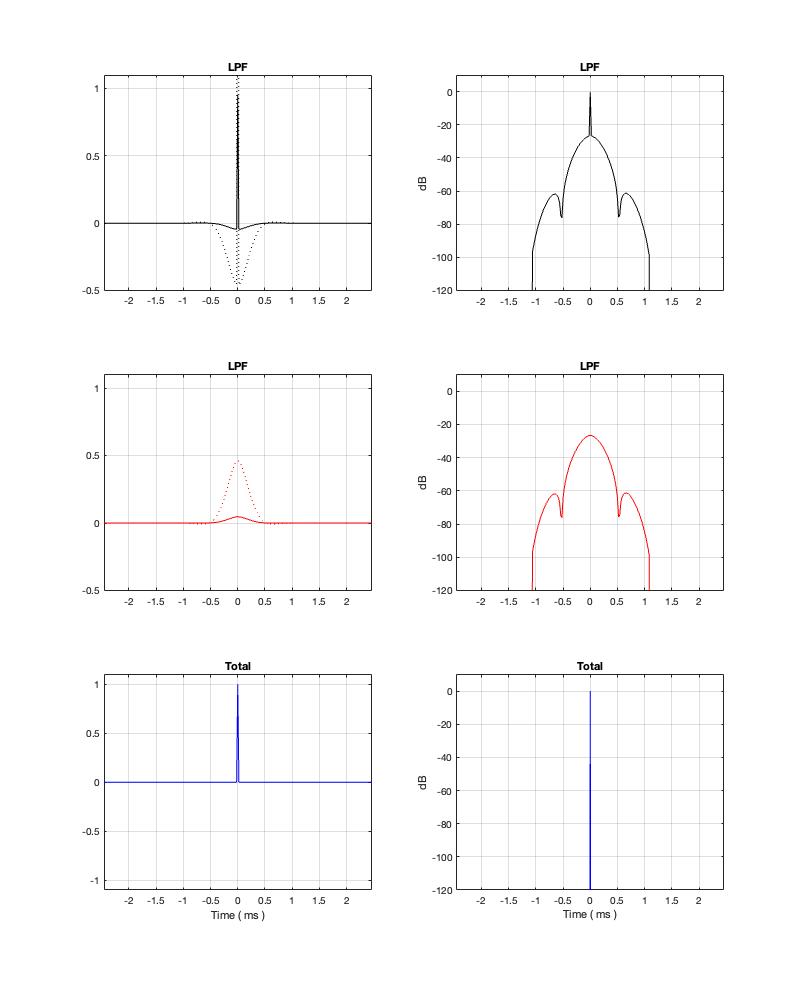
Hopefully, comparing the plot in Figure 13.1 and 13.2 helps to clarify the explanation above. Essentially, the plots in those two figures show the same thing. However, you can see in Figure 13.2 that I’ve cut off the impulse response once it drops below -250 dB.
The effect of doing this windowing can be seen in Figure 13.3 where you can see that the roll-off for the tweeter doesn’t keep going down in level as you drop in frequency. This is because the lower the frequency you want to filter, the longer the filter’s impulse response has to be.
Notice, however, that, despite the fact that the two magnitude responses in the top of Figure 13.3 aren’t exactly what you’re expect, the responses of the summed total are what you’d expect. This will become a familiar theme as we continue.
If we raise the threshold, we’ll shorten the impulse response, which means that we shorten the latency, and we deviate from the expected responses.
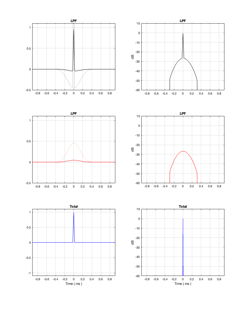
Figure 13.4: Fc = 1 kHz. Threshold = -100 dB Minimum Latency = 1.23 ms
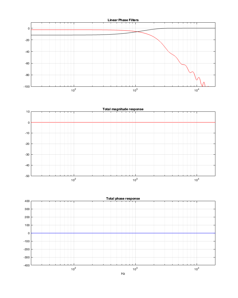
Figure 13.5: Fc = 1 kHz. Threshold = -100 dB
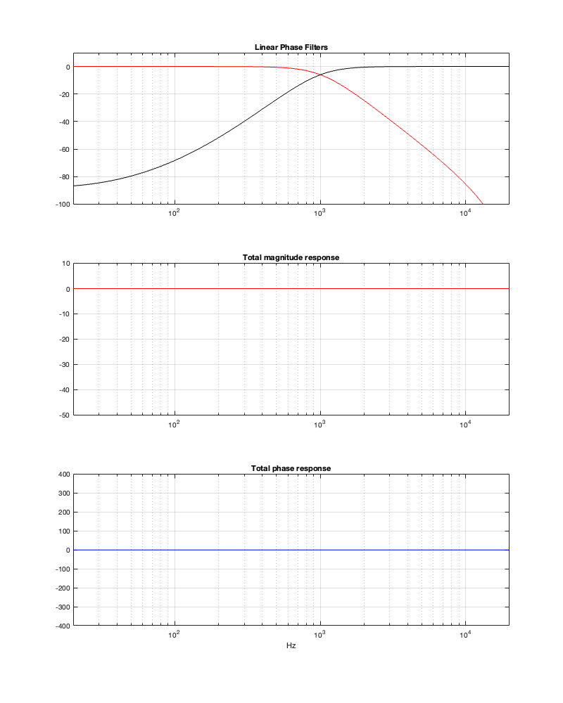
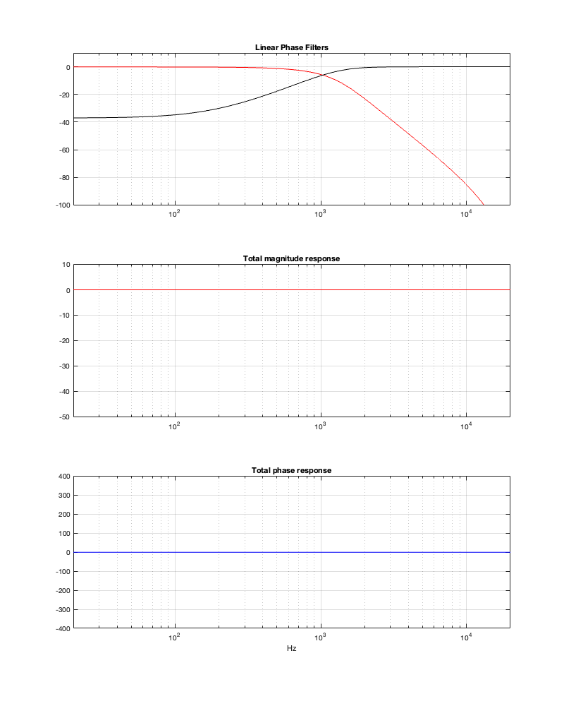
Notice in Figure 13.5 that, although the two crossover outputs have very different magnitude responses from 13.3, the total sum still works. Intuitively, this actually makes sense when you look at the impulse responses, since they still cancel each other – they’re just identical but opposite (except for the spike in the tweeter).
Of course, since the filter is now shorter in time, we get a lot more low-frequency output from the tweeter.
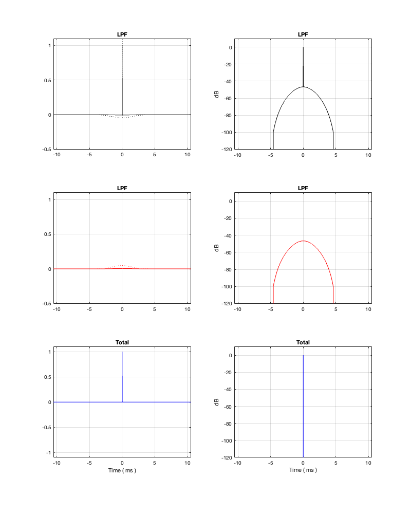
Figure 13.6: Fc = 1 kHz. Threshold = -50 dB Minimum Latency = 0.46 ms
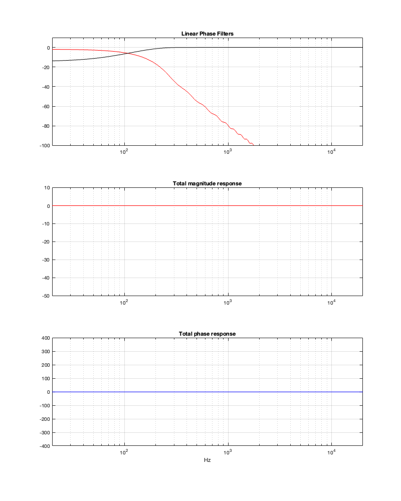
Figure 13.7: Fc = 1 kHz. Threshold = -50 dB
Notice in Figures 13.6 and 13.7 that, with a threshold of -50 dB, our latency can be under 0.5 ms. However, we will be expecting a lot of level out of the tweeter at low frequencies, which might be unhealthy for it if we turn up the volume.
Fc = 100 Hz
Now let’s repeat the process with a 100 Hz crossover to see what happens.
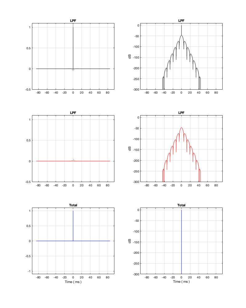
Figure 13.8: Fc = 100 Hz. Threshold = -250 dB Minimum Latency = 47.58 ms
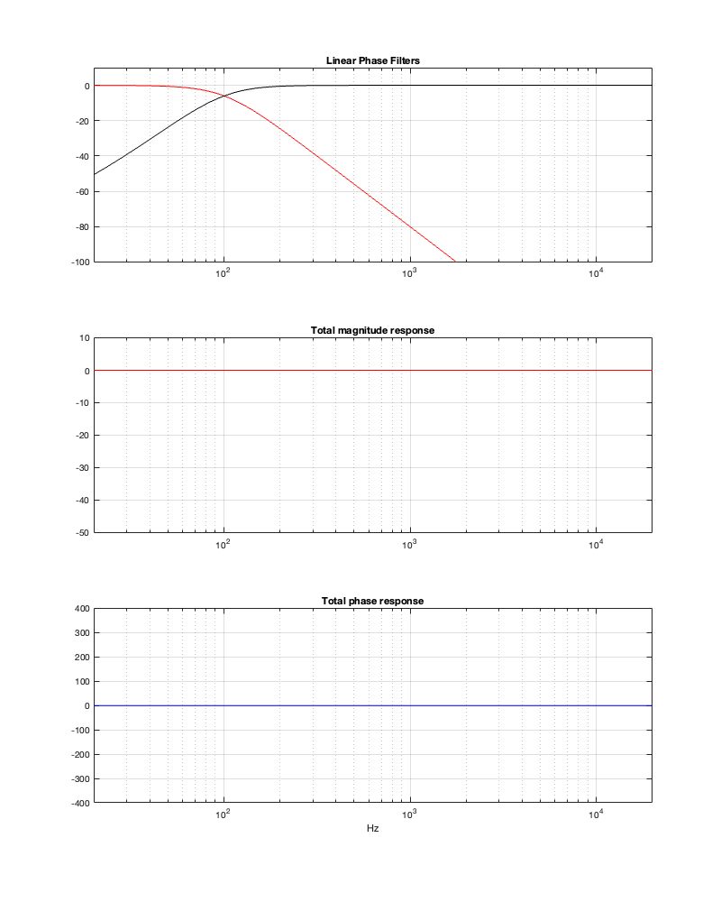
Figure 13.9: Fc = 100 Hz. Threshold = -250 dB
Notice that, in order to implement a threshold of -250 dB, we need at least about 47 ms of latency, which is probably outside acceptable limits for lip synch with video. It’s certainly far too long to be used in a loudspeaker for live sound, since you’ll hear and echo-echo all the time-time.
Figure 13.10: Fc = 100 Hz. Threshold = -100 dB Minimum Latency = 5.27 ms
Figure 13.11: Fc = 100 Hz. Threshold = -100 dB
Notice that, by changing to a threshold of -100 dB, we’ve dropped our latency requirement significantly – down to just over 5 ms. However, don’t trust everything you see there. This crossover probably won’t behave nicely… If we change the threshold to -50 dB, you can see where we’re headed, and why I am highly suspicious of the -100 dB filters…
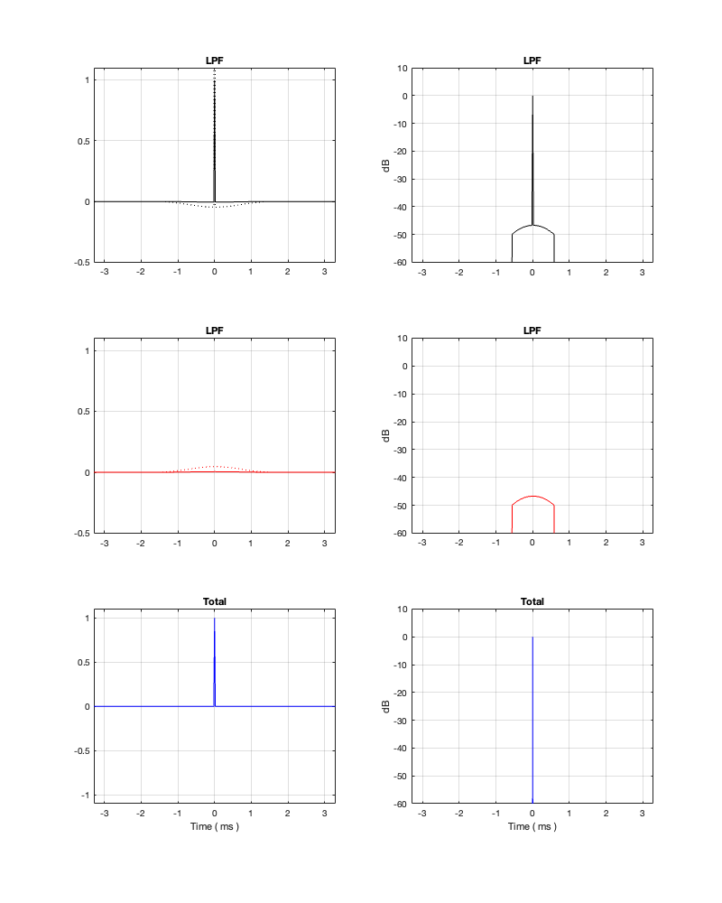
Figure 13.12: Fc = 100 Hz. Threshold = -50 dB Minimum Latency = 1.65 ms
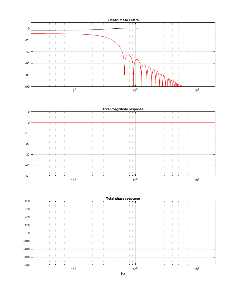
Figure 13.13: Fc = 100 Hz. Threshold = -50 dB
Obviously, that filter isn’t going to give you what you want – although it’ll give it to you quickly… (Editorial comment: It’s like current AI: it’s the fastest way to get the wrong answer…)
Wrapping up for now
Like I said above, regardless of how much I shorten these impulse responses, the responses of the summed outputs look good. This doesn’t necessarily mean that the crossover will work well, as should be evident by looking at the responses of the individual outputs.
In addition, it should be evident that, in order to implement a linear phase crossover that behaves well, you will incur a latency that may not be acceptable, depending on the crossover frequency and your requirements. Then again, if you don’t care about latency, you might start requiring a lot of computational power to implement it.
Like any aspect of crossover choice and design, there are multiple parameters to play with…
In the next posting, we’ll take a look at the implications of a linear phase crossover on the three-dimensional power response.