#45 in a series of articles about the technology behind Bang & Olufsen loudspeakers
Warning: In this page, I use a bunch of equations that might look very unfamiliar. These are called “s-domain expressions”, used in Laplace analysis. If these do not make any sense, don’t worry – it’s not really important that they do – so you can just skip over any math that looks ugly without guilt or concern. The reasons I used it here were twofold: firstly, these are taken from the equations in Bækgaard’s paper (mentioned below), and secondly, it’s the easiest way to show that something is missing (the “MissingPortion” in the intuitive equations below) in a two-way loudspeaker with one type of crossover.
When you build a two-way loudspeaker (one with a tweeter and a woofer), you have to divide the energy in the audio signal before sending it to the two drivers using a circuit called a crossover. This filters the signal sent to a tweeter using a high-pass filter (which only allows the high frequencies to pass through it) and the signal sent to the woofer using a low-pass filter (which allows the low frequencies to pass). The result is a signal that crosses over from the woofer to the tweeter as the frequency increases – hence the name. However, this is not necessarily the end of the solution, since high-pass and low-pass filters have some characteristics that we need to worry about.
One of those issues is that of the phase response of the filters. Although there are many different types of high-pass and low-pass filters, let’s take a simple example of the filters used in a second-order Butterworth two-way crossover – a very typical choice for passive loudspeaker designers.
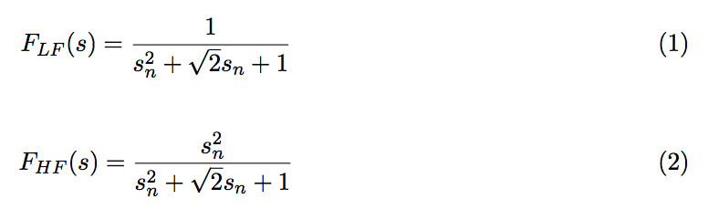
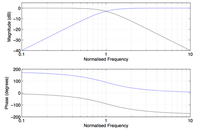
In a typical (second-order Butterworth) two-way crossover, the two bands are 180° out of phase as can be seen in the phase responses calculated using Equations 1 and 2 and plotted in Figure 1.
This phase difference isn’t a big problem at frequencies that are far away from the crossover frequency (where the two components have the same magnitude) because the quieter one isn’t loud enough to cancel the louder one very much. However, the closer you get to the crossover frequency, the more their magnitudes are alike, and so the more they cancel each other. In fact, at the crossover frequency itself, their magnitudes are identical, and, because they are 180° apart in phase, their sum is completely cancelled, resulting in no output at all. (Keep in mind here that, for the purposes of this posting, I’m living in a perfect world where loudspeaker drivers are perfectly linear, there are no time-of-arrival differences between the two drivers at the listening position, and things like diffraction and reflections do not exist…) The total result would therefore look like the responses shown in Figure 2.

To avoid complete cancellation at the crossover frequency where the two signals have identical magnitude, the polarity of the upper frequency band is typically inverted. (This is expressed as the negative sign at the beginning of the right-hand side of Equation 3). However, this solution results in a total sum that has a “bump” in its magnitude response as well as an allpass characteristic (meaning that the phase response of the total output is not a straight line).

At the listening position, on-axis to the loudspeaker, in this perfect world, these two frequency responses for the low frequency and high frequency sections (expressed in Equations 1 and 2) are combined using Equation 3.

In May 1977, Erik Bækgaard (pronounced something like BECK-gore), a manager of electronic engineering at B&O, published a paper in the Journal of the Audio Engineering Society where he described a solution to this problem associated with second-order Butterworth crossovers. Take a look at that last equation… Since we want the output to equal the input, we want F_Total(s) = 1. Therefore we can calculate what is missing from the s-plane equation to make that happen.
In other words, what we want is:

Bækgaard’s solution to this problem was to insert that component missing in Equation 5.

The frequency response of that resulting “MissingPortion” is a first-order bandpass filter with a phase response that is exactly between the phase responses of the high pass and low pass components, as can be seen in Figure 4, below. By adding that missing link to the system, the phase response of the entire system is corrected, so Bækgaard called the additional loudspeaker driver a “phase link” driver. So now, if we add the high pass, low pass and phase link components, we get the following:

… which means that the output of the system equals the input – exactly what we wanted!

Physically speaking, the solution to the problem was to add a third section in the crossover and an extra loudspeaker driver to fill in the missing phase component, linking the upper and lower frequency sections and avoiding the necessity for polarity inversion. This corrected the phase response of the entire system, eliminated the all pass characteristic and flattened the on-axis magnitude response, as can be seen in Figure 5.
The result was an entire range of loudspeakers, dubbed the “Uni-Phase” series, that was produced from 1976 to 1987. As is shown in Bækgaard’s paper, his system also improved the loudspeakers’ responses in the time domain, not only on-axis, but also off-axis in the vertical plane.

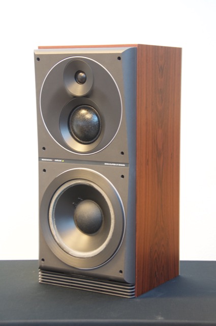
Figure 6, below, shows an example of one of the Uni-Phase loudspeakers. Without knowing what’s going on, it looks like a typical three-way loudspeaker with a woofer, midrange and tweeter. However, this is not the case. The woofer and the tweeter form a two-way loudspeaker and the middle driver is used as the Phase Link. So, instead of having two crossover frequencies, this loudspeaker has only one – and the peak in the bandpass response of the middle driver is at the same frequency as the crossover between the other two drivers.
Post-script: Of course, as I mentioned above, everything that I’ve said in this posting makes a lot of assumptions, not only about loudspeaker drivers, but cabinet effects and room acoustics. However, in order to keep things as simple as possible, it’s easier to isolate the issues described above as being the only problem with crossovers and loudspeakers. Sadly, this is not true…
Millemissen says:
Hi Geoff,
a couple of years ago there was a thread on Beoworld named ‘The “Uniphase” concept’:
http://forum.beoworld.org/forums/t/2523.aspx?PageIndex=1
that might interest you.
Jan Sand says:
Hi Geoff!
I vividly remember seeing this speaker at a HiFi fair in Stockholm when I was a kid. It was promoted by somekind of interactive cartoon character on a TV screen called “The Thumb”. He said about ordinary speakers: “Det låter lite burkigt”. It was very fun to read your post because I believed then, and probably many with me, that the main feature that made the speaker “faslinjär” (phase linear) was that the speaker front was not flat!
Maybe BO has always had a problem explaining their technological achievements, clouded as they are by beautiful design?!
All the best,
Jan
geoff says:
Hi Jan,
It might be fun to see the “Thumb” video. I wonder if it’s sitting on a hard drive somewhere in Struer… I’ll start asking around for this…
As for getting the technical information “cleanly” all the way to the customer – this is always a challenge for any company… But hopefully, B&O’s general efforts such as this blog site and the Technical Sound Guides are a way to address this.
Cheers
-geoff
Jeff says:
Interesting, a friend of mine who’s currently restoring a pair of M70s just got this paper from the AES.
I haven’t had time to wade thru the paper, and since retirement my math skills are rusty, but what effect does this have on power response compared to the more traditional inverting the driver polarity?
geoff says:
Hi Jeff,
Let me work on that one. It might take a week or three before I get around to it though…
Cheers
– geoff
Jeff says:
Hi Geoff,
Any further thoughts on how this effects power response?