Volume controls vs. Output levels

#92 in a series of articles about the technology behind Bang & Olufsen

One question people often ask about B&O loudspeakers is something like ”Why doesn’t the volume control work above 50%?”.

This is usually asked by someone using a small loudspeaker listening to pop music.

There are two reasons for this, related to the facts that there is such a wide range of capabilities in different Bang & Olufsen loudspeakers AND you can use them together in a surround or multiroom system. In other words for example, a Beolab 90 is capable of playing much, much more loudly than a Beolab 12; but they still have to play together.

Let’s use the example of a Beolab 90 and a Beolab 12, both playing in a surround configuration or a multiroom setup. In both cases, if the volume control is set to a low enough level, then these two types of loudspeakers should play at the same output level. This is true for quiet recordings (shown on the left in the figure below) and louder recordings (shown on the right).

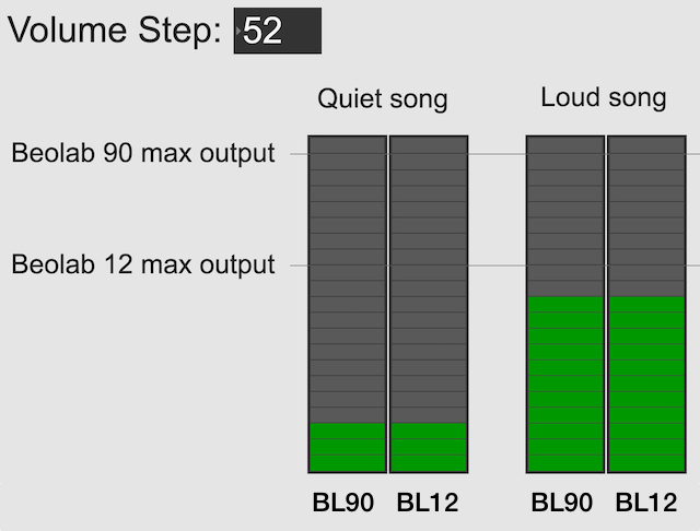
However, if you turn up the volume control, you will reach an output level that exceeds the capability of the Beolab 12 for the loud song (but not for the quiet song), shown in the figure below. At this point, for the loud song, the Beolab 12 has already begun to protect itself.

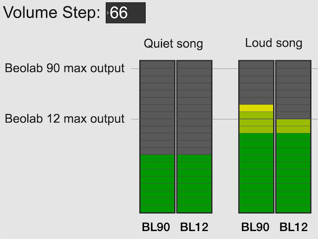
Once a B&O loudspeaker starts protecting itself, no matter how much more you turn it up, it will turn itself down by the same amount; so it won’t get louder. If it did get louder, it would either distort the sound or stop working – or distort the sound and then stop working.

If you ONLY own Beolab 12s and you ONLY listen to loud songs (e.g. pop and rock) then you might ask “why should I be able to turn up the volume higher than this?”.

The first answer is “because you might also own Beolab 90s” which can go louder, as you can see in the right hand side of the figure above.

The second answer is that you might want to listen to quieter recording (like a violin solo or a podcast). In this case, you haven’t reached the maximum output of even the Beolab 12 yet, as you can see in the left hand side of the figure above. So, you should be able to increase the volume setting to make even the quiet recording reach the limits of the less-capable loudspeaker, as shown below.

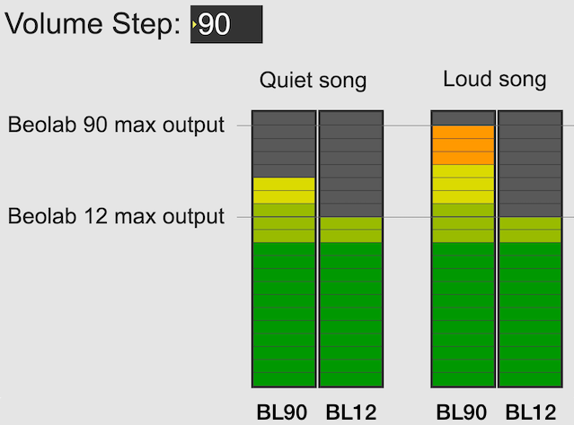
Notice, however, that at this high volume setting, both the quiet recording and the loud recording have the same output level on the Beolab 12.

So, the volume allows you to push the output higher; either because you might also own more capable loudspeakers (maybe not today – but some day) OR because you’re playing a quiet recording and you want to hear it over the sound of the exhaust fan above your stove or the noise from your shower.

It’s also good to remember that the volume control isn’t an indicator of how loud the output should be. It’s an indicator of how much quieter or louder you’re making the input signal.

The volume control is more like how far down you’re pushing the accelerator in your car – not the indication of the speedometer. If you push down the accelerator 50% of the way, your actual speed is dependent on many things like what gear you’re in, whether you’re going uphill or downhill, and whether you’re towing a heavy trailer. Similarly Metallica at volume step 70 will be much louder than a solo violin recording at the same volume step, unless you are playing it through a loudspeaker that reached its maximum possible output at volume step 50, in which case the Metallica and the violin might be the same level.

Note 1: For all of the above, I’ve said “quiet song” and “loud song” or “quiet recording” and “loud recording” – but I could just have easily as said “quiet part of the song” and “loud part of the song”. The issue is not just related to mastering levels (the overall level of the recording) but the dynamic range (the “distance” between the quietest and the loudest moment of a recording).

Note 2: I’ve written a longer, more detailed explanation of this in Posting #81: Turn it down half-way.

B&O Pickup stylus comparison

Below are four photos taken with the same magnification.

The top two photos are a Bang & Olufsen SP2 pickup, compatible with the 25º tonearm on a Type 42 “Stereopladespiller”.

The bottom two are a rather dirty Bang & Olufsen MMC 1/2 pickup, compatible with a range of turntables including the Beogram 4500, for example.

The yellow grid lines have a 0.50 mm spacing.

What is a “virtual” loudspeaker? Part 3

#91.3 in a series of articles about the technology behind Bang & Olufsen

In Part 1 of this series, I talked about how a binaural audio signal can (hypothetically, with HRTFs that match your personal ones) be used to simulate the sound of a source (like a loudspeaker, for example) in space. However, to work, you have to make sure that the left and right ears get completely isolated signals (using earphones, for example).

In Part 2, I showed how, with enough processing power, a large amount of luck (using HRTFs that match your personal ones PLUS the promise that you’re in exactly the correct location), and a room that has no walls, floor or ceiling, you can get a pair of loudspeakers to behave like a pair of headphones using crosstalk cancellation.

There’s not much left to do to create a virtual loudspeaker. All we need to do is to:

  • Take the signal that should be sent to a right surround loudspeaker (for example) and filter it using the HRTFs that correspond to a sound source in the location that this loudspeaker would be in. REMEMBER that this signal has to get to your two ears since you would have used your two ears to hear an actual loudspeaker in that location.
  • Send those two signals through a crosstalk cancellation processing system that causes your two loudspeakers to behave more like a pair of headphones.
Figure 1: A block diagram of the system described above.

One nice thing about this system is that the crosstalk cancellation is only there to ensure that the actual loudspeakers behave more like headphones. So, if you want to create more virtual channels, you don’t need to duplicate the crosstalk cancellation processor. You only need to create the binaurally-processed versions of each input signal and mix those together before sending the total result to the crosstalk cancellation processor, as shown below.

Figure 2: You only need one crosstalk cancellation system for any number of virtual channels.

This is good because it saves on processing power.

So, there are some important things to realise after having read this series:

  • All “virtual” loudspeakers’ signals are actually produced by the left and right loudspeakers in the system. In the case of the Beosound Theatre, these are the Left and Right Front-firing outputs.
  • Any single virtual loudspeaker (for example, the Left Surround) requires BOTH output channels to produce sound.
  • If the delays (aka Speaker Distance) and gains (aka Speaker Levels) of the REAL outputs are incorrect at the listening position, then the crosstalk cancellation will not work and the virtual loudspeaker simulation system won’t work. How badly is doesn’t work depends on how wrong the delays and gains are.
  • The virtual loudspeaker effect will be experienced differently by different persons because it’s depending on how closely your actual personal HRTFs match those predicted in the processor. So, don’t get into fights with your friends on the sofa about where you hear the helicopter…
  • The listening room’s acoustical behaviour will also have an effect on the crosstalk cancellation. For example, strong early reflections will “infect” the signals at the listening position and may/will cause the cancellation to not work as well. So, the results will vary not only with changes in rooms but also speaker locations.

Finally, it’s worth nothing that, in the specific case of the Beosound Theatre, by setting the Speaker Distances and Speaker Levels for the Left and Right Front-firing outputs for your listening position, then you have automatically calibrated the virtual outputs. This is because the Speaker Distances and Speaker Levels are compensations for the ACTUAL outputs of the system, which are the ones producing the signal that simulate the virtual loudspeakers. This is the reason why the four virtual loudspeakers do not have individual Speaker Distances and Speaker Levels. If they did, they would have to be identical to the Left and Right Front-firing outputs’ values.

What is a “virtual” loudspeaker? Part 2

#91.2 in a series of articles about the technology behind Bang & Olufsen

In Part 1, I talked at how a binaural recording is made, and I also mentioned that the spatial effects may or may not work well for you for a number of different reasons.

Let’s go back to the free field with a single “perfect” microphone to measure what’s happening, but this time, we’ll send sound out of two identical “perfect” loudspeakers. The distances from the loudspeakers to the microphone are identical. The only difference in this hypothetical world is that the two loudspeakers are in different positions (measuring as a rotational angle) as shown in Figure 1.

Figure 1: Two identical, “perfect” loudspeakers in a free field with a single “perfect” microphone.

In this example, because everything is perfect, and the space is a free field, then output of the microphone will be the sum of the outputs of the two loudspeakers. (In the same way that if your dog and your cat are both asking for dinner simultaneously, you’ll hear dog+cat and have to decide which is more annoying and therefore gets fed first…)

Figure 2: The output from the microphone is the sum of the outputs from the two loudspeakers. At any moment in time, the value of the top plot + the value of the middle plot = the value of the bottom plot.

IF the system is perfect as I described above, then we can play some tricks that could be useful. For example, since the output of the microphone is the sum of the outputs of the two loudspeakers, what happens if the output of one loudspeaker is identical to the other loudspeaker, but reversed in polarity?

Figure 3: If the output of Loudspeaker 1 is exactly the same as the output of Loudspeaker 2 except for polarity, then the sum (the output of the microphone) is always 0.

In this example, we’re manipulating the signals so that, when they add together, you nothing at the output. This is because, at any moment in time, the value of Loudspeaker 2’s output is the value of Loudspeaker 1’s output * -1. So, in other words, we’re just subtracting the signal from itself at the microphone and we get something called “perfect cancellation” because the two signals cancel each other at all times.

Of course, if anything changes, then this perfect cancellation won’t work. For example, if one of the loudspeakers moves a little farther away than the other, then the system is broken, as shown below.

Figure 4: A small shift in time in the output of Loudspeaker 2 cases the cancellation to stop working so well.

Again, everything that I’ve said above only works when everything is perfect, and the loudspeakers and the microphone are in a free field; so there are no reflections coming in and ruining everything.

We can now combine these two concepts:

  1. using binaural signals to simulate a sound source in a location (although this would normally be done using playback over earphones to keep it simple) and
  2. using signals from loudspeakers to cancel each other at some location in space as a

to create a system for making virtual loudspeakers.

Let’s suspend our adherence to reality and continue with this hypothetical world where everything works as we want… We’ll replace the microphone with a person and consider what happens. To start, let’s just think about the output of the left loudspeaker.

Figure 5: The output of the left loudspeaker reaches both ears with different time/frequency characteristics caused by the HRTF associated with that sound source location.

If we plot the impulse responses at the two ears (the “click” sound from the loudspeaker after it’s been modified by the HRTFs for that loudspeaker location), they’ll look like this:

Figure 6: The impulse responses of the HRTFs for a sound source at 30º left of centre.

What if were were able to send a signal out of the right loudspeaker so that it cancels the signal from the left loudspeaker at the location of the right eardrum?

Figure 7: What if we could cancel the signal from the left loudspeaker at the right ear using the right loudspeaker?

Unfortunately, this is not quite as easy as it sounds, since the HRTF of the right loudspeaker at the right ear is also in the picture, so we have to be a bit clever about this.

So, in order for this to work we:

  • Send a signal out of the left loudspeaker.
    We know that this will get to the right eardrum after it’s been messed up by the HRTF. This is what we want to cancel…
  • …so we take that same signal, and
    • filter it with the inverse of the HRTF of the right loudspeaker
      (to undo the effects of the HRTF of the right loudspeaker’s signal at the right ear)
    • filter that with the HRTF of the left loudspeaker at the right ear
      (to match the filtering that’s done by your head and pinna)
    • multiply by -1
      (so that it will cancel when everything comes together at your right eardrum)
    • and send it out the right loudspeaker.

Hypothetically, that signal (from the right loudspeaker) will reach your right eardrum at the same time as the unprocessed signal from the left loudspeaker and the two will cancel each other, just like the simple example shown in Figure 3. This effect is called crosstalk cancellation, because we use the signal from one loudspeaker to cancel the sound from the other loudspeaker that crosses to the wrong side of your head.

This then means that we have started to build a system where the output of the left loudspeaker is heard ONLY in your left ear. Of course, it’s not perfect because that cancellation signal that I sent out of the right loudspeaker gets to the left ear a little later, so we have to cancel the cancellation signal using the left loudspeaker, and back and forth forever.

If, at the same time, we’re doing the same thing for the other channel, then we’ve built a system where you have the left loudspeaker’s signal in the left ear and the right loudspeaker’s signal in the right ear; just like a pair of headphones!

However, if you get any of these elements wrong, the system will start to under-perform. For example, if the HRTFs that I use to predict your HRTFs are incorrect, then it won’t work as well. Or, if things aren’t time-aligned correctly (because you moved) then the cancellation won’t work.

on to Part 3

What is a “virtual” loudspeaker? Part 1

#91.1 in a series of articles about the technology behind Bang & Olufsen

Without connecting external loudspeakers, Bang & Olufsen’s Beosound Theatre has a total of 11 independent outputs, each of which can be assigned any Speaker Role (or input channel). Four of these are called “virtual” loudspeakers – but what does this mean? There’s a brief explanation of this concept in the Technical Sound Guide for the Theatre (you’ll find the link at the bottom of this page), which I’ve duplicated in a previous posting. However, let’s dig into this concept a little more deeply.

To begin, let’s put a “perfect” loudspeaker in a free field. This means that it’s in a space that has no surfaces to reflect the sound – so it’s an acoustic field where the sound wave is free to travel outwards forever without hitting anything (or at least appear as this is the case). We’ll also put a “perfect” microphone in the same space.

Figure 1: A loudspeaker and a microphone (the circle) in a free field: an infinite space completely free of reflective surfaces.

We then send an impulse; a very short, very loud “click” to the loudspeaker. (Actually a perfect impulse is infinitely short and infinitely loud, but this is not only inadvisable but impossible, and probably illegal.)

Figure 2: The “click” signal that’s sent to the input of the loudspeaker.

That sound radiates outwards through the free field and reaches the microphone which converts the acoustic signal back to an electrical one so we can look at it.

Figure 3: The “click” signal that is received at the microphone’s location and sent out as an electrical signal.

There are three things to notice when you compare Figure 3 to Figure 2:

  • The signal’s level is lower. This is because the microphone is some distance from the loudspeaker.
  • The signal is later. This is because the microphone is some distance from the loudspeaker and sound waves travel pretty slowly.
  • The general shape of the signals are identical. This is because I said that the loudspeaker and the microphone were both “perfect” and we’re in a space that is completely free of reflections.

What happens if we take away the microphone and put you in the same place instead?

Figure 4: The microphone has been replaced by something more familiar.

If we now send the same click to the loudspeaker and look at the “outputs” of your two eardrums (the signals that are sent to your brain), these will look something like this:

Figure 5: The outputs of your two eardrums with the same “click” signal from the loudspeaker.

These two signals are obviously very different from the one that the microphone “hears” which should not be a surprise: ears aren’t microphones. However, there are some specific things of which we should take note:

  • The output of the left eardrum is lower than that of the right eardrum. This is largely because of an effect called “head shadowing” which is exactly what it sounds like. The sound is quieter in your left ear because your head is in the way.
  • The signal at the right eardrum is earlier than at the left eardrum. This is because the left eardrum is not only farther away, but the sound has to go around your head to get there.
  • The signal at the right eardrum is earlier than the output of the microphone output (in Figure 3) because it’s closer to the loudspeaker. (I put the microphone at the location of the centre of the simulated head.) Similarly the left ear output is later because it’s farther away.
  • The signal at the right eardrum is full of spikes. This is mostly caused by reflections off the pinna (the flappy thing on the side of your head that you call your “ear”) that arrive at slightly different times, and all add together to make a mess.
  • The signal at the left eardrum is “smoother”. This is because the head itself acts as a filter reducing the levels of the high frequency content, which tends to make things less “spiky”.
  • Both signals last longer in time. This is the effect of the ear canal (the “hole” in the side of your head that you should NOT stick a pencil in) resonating like a little organ pipe.

The difference between the signals in Figures 2 and 4 is a measurement of the effect that your head (including your shoulders, ears/pinnae) has on the transfer of the sound from the loudspeaker to your eardrums. Consequently, we geeks call it a “head-related transfer function” or HRTF. I’ve plotted this HRTF as a measurement of an impulse in time – but I could have converted it to a frequency response instead (which would include the changes in magnitude and phase for different frequencies).

Here’s the cool thing: If I put a pair of headphones on you and played those two signals in Figure 5 to your two ears, you might be able to convince yourself that you hear the click coming from the same place as where that loudspeaker is located.

Although this sounds magical, don’t get too excited right away. Unfortunately, as with most things in life, reality tends to get in the way for a number of reasons:

  • Your head and ears aren’t the same shape as anyone else’s. Your brain has lived with your head and your ears for a long time, and it’s learned to correlate your HRTFs with the locations of sound sources. If I suddenly feed you a signal that uses my HRTFs, then this trick may or may not work, depending on how similar we are. This is just like borrowing someone else’s glasses. If you have roughly the same prescription, then you can see. However, if the prescriptions are very different, you’ll get a headache very quickly.
  • In reality, you’re always moving. So, even if the sound source is not moving, the specific details of the HRTFs are always changing (because the relative positions and angles to your ears are changing) but my system doesn’t know about this – so I’m simulating a system where the loudspeaker moves around you as you rotate your head. Since this never happens in real life, it tends to break the simulation.
  • The stuff I showed above doesn’t include reflections, which is how you determine distance to sources. If I wanted to include reflections, each reflection would have to have its own HRTF processing, depending on its angle relative to your head.

However, hypothetically, this can work, and lots of people have tried. The easiest way to do this is to not bother measuring anything. You just take a “dummy head” -a thing that is the same size as an average human head (maybe with an average torso) and average pinnae* – but with microphones where the eardrums are – and you plunk it down in a seat in a concert hall and record the outputs of the two “ears”. You then listen to this over earphones (we don’t use headphones because we want to remove your pinnae from the equation) and you get a “you are there” experience (assuming that the dummy head’s dimensions and shape are about the same as yours). This is what’s known as a binaural recording because it’s a recording that’s done with two ears (instead of two or more “simple” microphones).

If you want to experience this for yourself, plug a pair of headphones into your computer and do a search for the “Virtual Barber Shop” video. However, if you find that it doesn’t work for you, don’t be upset. It just means that you’re different: just like everyone else.* Typically, recordings like this have a strange effect of things sounding very close in the front, and farther away as sources go to the sides. (Personally, I typically don’t hear anything in the front. All of the sources sound like they’re sitting on the back of my neck and shoulders. This might be because I have a fat head (yes, yes… I know…) and small pinnae (yes, yes…. I know…) – or it might indicate some inherent paranoia of which I am not conscious.)

* Of course, depressingly typically, it goes without saying that the sizes and shapes of commercially-available dummy heads are based on averages of measurements of men only. Neither women nor children are interested in binaural recordings or have any relevance to such things, apparently…

on to Part 2

Beosound Theatre: Virtual loudspeakers

#90 in a series of articles about the technology behind Bang & Olufsen

Devices such as the ‘stereoscope’ for representing photographs (and films) in three-dimensions have been around since the 1850s. These work by presenting two different photographs with slightly different perspectives two the two eyes. If the differences in the photographs are the same as the differences your eyes would have seen had you ‘been there’, then your brain interprets into a 3D image.

A similar trick can be done with sound sources. If two different sounds that exactly match the signals that you would have heard had you ‘been there’ are presented at your two ears (using a binaural recording) , then your brain will interpret the signals and give you the auditory impression of a sound source in some position in space. The easiest way to do this is to ensure that the signals arriving at your ears are completely independent using headphones.

The problem with attempting this with loudspeaker reproduction is that there is ‘crosstalk’ or ‘bleeding of the signals to the opposite ears’. For example, the sound from a correctly-positioned Left Front loudspeaker can be heard by your left ear and your right ear (slightly later, and with a different response). This interference destroys the spatial illusion that is encoded in the two audio channels of a binaural recording.

However, it might be possible to overcome this issue with some careful processing and assumptions. For example, if the exact locations of the left and right loudspeakers and your left and right ears are known by the system, then it’s (hypothetically) possible to produce a signal from the right loudspeaker that cancels the sound of the left loudspeaker in the right ear, and therefore you only hear the left channel in the left ear. (Of course, the cancelling signal of the right loudspeaker also bleeds to the left ear, so the left loudspeaker has to be used to cancel the cancellation signal of the right loudspeaker in the left ear, and so on…)

Using this ‘crosstalk cancellation’ processing, it becomes (hypothetically) possible to make a pair of loudspeakers behave more like a pair of headphones, with only the left channel in the left ear and the right in the right. Therefore, if this system is combined with the binaural recording / reproduction system, then it becomes (hypothetically) possible to give a listener the impression of a sound source placed at any location in space, regardless of the actual location of the loudspeakers.

Theory vs. Reality

It’s been said that the difference between theory and practice is that, in theory, there is no difference between theory and practice, whereas in practice, there is. This is certainly true both of binaural recordings (or processing) and crosstalk cancellation.

In the case of binaural processing, in order to produce a convincing simulation of a sound source in a position around the listener, the simulation of the acoustical characteristics of a particular listener’s head, torso, and (most importantly) pinnae (a.k.a. ‘ears’) must be both accurate and precise. (For the same reason that someone else should not try to wear my glasses.)

Similarly, a crosstalk cancellation system must also have accurate and precise ‘knowledge’ of the listener’s physical characteristics in order to cancel the signals correctly; but this information also crucially includes the exact locations of the

loudspeakers and the listener (we’ll conveniently pretend that the room you’re sitting in does not exist).

In the end, this means that a system with adequate processing power can use two loudspeakers to simulate a ‘virtual’ loudspeaker in another location. However, the details of that spatial effect will be slightly different from person to person (because we’re all shaped differently). Also, more importantly, the effect will only be experienced by a listener who is positioned correctly in front of the loudspeakers. Slight movements (especially from side-to-side, which destroys the symmetrical time-of-arrival matching of the two incoming signals) will cause the illusion to collapse.

Beosound Theatre gives you the option to choose Virtual Loudspeakers that appear to be located in four different positions: Left and Right Wide, and Left and Right Elevated. These signals are actually produced using the Left and Right front-firing outputs of the device using this combination of binaural processing and crosstalk cancellation in the Dolby Atmos processing system. If you are a single listener in the correct position (with the Speaker Distances and Speaker Levels adjusted correctly) then the Virtual outputs come very close to producing the illusion of correctly-located Surround and Front Height loudspeakers.

However, in cases where there is more than one listener, or where a single listener may be incorrectly located, it may be preferable to use the ‘side-firing’ and ‘up-firing’ outputs instead.

Keep your needle clean

One of my jobs at Bang & Olufsen is to do the final measurements on each bespoke Beogram 4000c turntable before it’s sent to the customer. Those measurements include checking the end-to-end magnitude response, playing from a vinyl record with a sine sweep on it (one per channel), recording that from the turntable’s line-level output, and analysing it to make sure that it’s as expected. Part of that analysis is to very that the magnitude responses of the left and right channel outputs are the same (or, same enough… it’s analogue, a world where nothing is perfect…)

Today, I was surprised to see this result on a turntable that was being inspected part-way through its restoration process :

Taken at face value, this should have resulted in a rejection – or at least some very serious questions. This is a terrible result, with unacceptable differences in output level between the two channels. When I looked at the raw measurements, I could easily see that the left channel was behaving – it was the right channel that was all over the place.

The black curve looks very much like what I would expect to see. This is the result of playing a track that is a sine sweep from 20 Hz to 20 kHz, where the signal below 1 kHz follows the RIAA curve, whereas the signal above 1 kHz does not. This is why, after it’s been filtered using a RIAA preamp, the low frequency portion has a flat response, but the upper frequency band rolls off (following the RIAA curve).

Notice that the right channel (the red curve) is a mess…

A quick inspection revealed what might have been the problem: a small ball of fluff collected around the stylus. (This was a pickup that was being used to verify that the turntable was behaving through the restoration – not the one intended for the final customer – and so had been used multiple times on multiple turntables.)

So, we used a stylus brush to clean off the fluff and ran the measurement again. The result immediately afterwards looked like this:

which is more like it! A left-right channel difference of something like ± 0.5 dB is perfectly acceptable.

The moral of the story: keep your pickup clean. But do it carefully! That cantilever is not difficult to snap.

Beosound Theatre: Spatial control

#89 in a series of articles about the technology behind Bang & Olufsen

There are many cases where the number of input channels in the audio signal does not match the number of loudspeakers in your configuration. For example, you may have two loudspeakers, but the input signal is from a multichannel source such as a 7.1-channel stream or a 7.1.4-channel Blu-ray. In this case, the audio must be ‘downmixed’ to your two loudspeakers if you are to hear all components of the audio signal. Conversely, you may have a full surround sound system with 7 main loudspeakers and a subwoofer (a 7.1-channel system) and you would like to re-distribute the two channels from a CD to all of your loudspeakers. In this example, the signal must be ‘upmixed’ to all loudspeakers.

Bang & Olufsen’s True Image is a processor that accomplishes both of these tasks dynamically, downmixing or upmixing any incoming signal so that all components and aspects of the original recording are played using all of your loudspeakers.

Of course, using the True Image processor means that signals in the original recording are re-distributed. For example, in an upmixing situation, portions in the original Left Front signal from the source will be sent to a number of loudspeakers in your system instead of just one left front loudspeaker. If you wish to have a direct connection between input and output channels, then the Processing should be set to ‘Direct’, thus disabling the True Image processing.

Note that, in Direct mode, there may be instances where some input or output channels will not be audible. For example, if you have two loudspeakers but a multichannel input, only two of the input channels will be audible. These channels are dependent on the speaker roles selected for the two loudspeakers. (For example, if your loudspeakers’ roles are Left Front and Right Front, then only the Left Front and Right Front channels from the multichannel source will be heard.)

Similarly, in Direct mode, if you have a multichannel configuration but a two-channel stereo input, then only the loudspeakers assigned to have the Left Front and Right Front speaker roles will produce the sound; all other loudspeakers will be silent.

If True Image is selected and if the number of input channels and their channel assignments matches the speaker roles, and if all Spatial Control sliders are set to the middle position, then the True Image processing is bypassed. For example, if you have a 5.1 loudspeaker system with 5 main loudspeakers (Left Front, Right Front, Centre Front, Left Surround, and Right Surround) and a subwoofer, and the Spatial Control sliders are in the middle positions, then a 5.1 audio signal (from a DVD, for example) will pass through unaffected.

However, if the input is changed to a 2.0 source (i.e. a CD or an Internet radio stream) then the True Image processor will upmix the signal to the 5.1 outputs.

In the case where you wish to have the benefits of downmixing without the spatial expansion provided by upmixing, you can choose to use the Downmix setting in this menu. For example, if you have a 5.1-channel loudspeaker configuration and you wish to downmix 6.1- and 7.1-channel sources (thus ensuring that you are able to hear all input channels) but that two-channel stereo sources are played through only two loudspeakers, then this option should be selected. Note that, in Downmix mode, there are two exceptions where upmixing may be applied to the signal. The first of these is when you have a 2.0-channel loudspeaker configuration and a 1-channel monophonic input. In this case, the centre front signal will be distributed to the Left Front and Right Front loudspeakers. The second case is when you have a 6.1 input and a 7.1 loudspeaker configuration. In this case, the Centre Back signal will be distributed to the Left Back and Right Back loudspeakers.

The Beosound Theatre includes four advanced controls (Surround, Height, Stage Width and Envelopment, described below) that can be used to customise the spatial attributes of the output when the True Image processor is enabled.

Surround

The Surround setting allows you to determine the relative levels of the sound stage (in the front) and the surround information from the True Image processor.

Changes in the Surround setting only have an effect on the signal when the Processing is set to True Image.

Height

This setting determines the level of the signals sent to all loudspeakers in your configuration with a ‘height’ Speaker Role. It will have no effect on other loudspeakers in your system.

If the setting is set to minimum, then no signal will be sent to the ‘height’ loudspeakers.

Changes in the Height setting only have an effect on the signal when the Processing is set to True Image.

Stage Width

The Stage Width setting can be used to determine the width of the front images in the sound stage. At a minimum setting, the images will collapse to the centre of the frontal image. At a maximum setting, images will be pushed to the sides of the front sound stage. This allows you to control the perceived width of the band or music ensemble without affecting the information in the surround and back loudspeakers.

If you have three front loudspeakers (Left Front, Right Front and Centre Front), the setting of the Stage Width can be customised according to your typical listening position. If you normally sit in the ‘sweet spot’, at roughly the same distance from all three loudspeakers, then you should increase the Stage Width setting somewhat, since it is unnecessary to use the centre front loudspeaker to help to pull phantom images towards the centre of the sound stage. The further to either side of the sweet spot that you are seated, the more reducing the Stage Width value will improve the centre image location.

Changes in the Stage Width setting only have an effect on the signal when the Processing is set to True Image.

Envelopment

The Envelopment setting allows you to set the desired amount of perceived width or spaciousness from your surround and back loudspeakers. At its minimum setting, the surround information will appear to collapse to a centre back phantom location. At its maximum setting, the surround information will appear to be very wide.

Changes in this setting have no effect on the front loudspeaker channels and only have an effect on the signal when the Processing is set to True Image.

One last point…

One really important thing to know about the True Image processor is that, if the input signal’s configuration matches the output, AND the 4 sliders described above are in the middle positions, then True Image does nothing. In other words, in this specific case, it’s the same as ‘Direct’ mode.

However, if there is a mis-match between the input and the output channel configuration (for example, 2.0 in and 5.1 out, or 7.1.4 in and 5.1.2 out) then True Image will do something: either upmixing or downmixing. Also, if the input configuration matches the output configuration (e.g. 5.x in and 5.x out) but you’ve adjusted any of the sliders, then True Image will also do something…

Beosound Theatre and Dolby Atmos

#88 in a series of articles about the technology behind Bang & Olufsen

In 2012, Dolby introduced its Dolby Atmos surround sound technology in movie theatres with the release of the Pixar movie, ‘Brave’, and support for the system was first demonstrated on equipment for home theatres in 2014. However, in spite of the fact that it has been 10 years since its introduction, it still helps to offer an introductory explanation to what, exactly, Dolby Atmos is. For more in-depth explanations, https://www.dolby.com/technologies/dolby-atmos is a good place to start and https://www.dolby.com/about/support/guide/speaker-setup-guides has a wide range of options for loudspeaker configuration recommendations.

From the perspective of audio / video systems for the home, Dolby Atmos can most easily be thought of as a collection of different things:

  1. a set of recommendations for loudspeaker configuration that can include loudspeakers located above the listening position
  2. a method of supplying audio signals to those loudspeakers that not only use audio channels that are intended to be played by a single loudspeaker (e.g. Left Front or Right Surround), but also audio objects whose intended spatial positions are set by the mixing engineer, but whose actual spatial position is ‘rendered’ based on the actual loudspeaker configuration in the customer’s listening room.
  3. a method of simulating the spatial positions of ‘virtual’ loudspeakers
  4. the option to use loudspeakers that are intentionally directed away from the listening position, potentially increasing the spatial effects in the mix. These are typically called ‘up-firing’ and ‘side-firing’ loudspeakers.

In addition to this, Dolby has other technologies that have been enhanced to be used in conjunction with Dolby Atmos-encoded signals. Arguably, the most significant of these is an upmixing / downmixing algorithm that can adapt the input signal’s configuration to the output channels.

Note that many online sites state that Dolby’s upmixing / downmixing processor is part of the Dolby Atmos system. This is incorrect. It’s a separate processor.

1. Loudspeaker configurations

Dolby’s Atmos recommendations allow for a large number of different options when choosing the locations of the loudspeakers in your listening room. These range from a simple 2.0.0, traditional two-channel stereo loudspeaker configuration up to a 24.1.10 large-scale loudspeaker array for movie theatres. The figures below show a small sampling of the most common options. (see https://www.dolby.com/about/support/guide/speaker-setup-guides/ for many more possibilities and recommendations.)

Standard loudspeaker configuration for two-channel stereo (Lf / Rf)

Standard loudspeaker configuration for 5.x multichannel audio. The actual angles of the surround loudspeakers at 110 degrees shows the reference placement used at Bang & Olufsen for testing and tuning. Note that the placement of the subwoofer is better determined by your listening room’s acoustics, but it is advisable to begin with a location near the centre front loudspeaker.

Recommended loudspeaker configuration for most 7.x channel audio signals. The actual angles of the loudspeakers shows the reference placement used at Bang & Olufsen for testing and tuning.
Loudspeaker positions associated with the speaker roles available in the Beosound Theatre, showing a full 7.x.4 configuration.

Loudspeaker positions associated with the speaker roles available in the Beosound Theatre, showing a full 7.x.4 configuration.

2. Channels and Objects

Typically, when you listen to audio, regardless of whether it’s monophonic or a stereo (remember that ‘stereo’ merely implies ‘more than one channel’) signal, you are reproducing some number of audio channels that were mixed in a studio. For example, a recording engineer placed a large number of microphones around a symphony orchestra or a jazz ensemble, and then decided on the mix (or relative balance) of those signals that should be sent to a loudspeakers in the left front and right front positions. They did this by listening to the mix through loudspeakers in a standard configuration with the intention that you place your loudspeakers similarly and sit in the correct location.

Consequently, each loudspeaker’s input can be thought of as receiving a ‘pre-packaged’ audio channel of information.

However, in the early 2000s, a new system for delivering audio to listeners was introduced with the advent of powerful gaming consoles. In these systems, it was impossible for the recording engineer to know where a sound should be coming from at any given moment in a game with moving players. So, instead of pre-mixing sound effects (like footsteps, for example) in a fixed position, a monophonic recording of the effect (the footsteps) was stored in the game’s software, and then the spatial position could be set at the moment of playback. So, if the footsteps should appear on the player’s left, then the game console would play them on the left. If the player then turned, the footsteps could be moved to appear in the centre or on the right. In this way different sound objects could be ‘rendered’ instead of merely being reproduced. Of course, the output of these systems was still either loudspeakers or headphones; so the rendered sound objects were mixed with the audio channels (e.g. background music) before being sent to the outputs.

The advantage of a channel-based system is that there is (at least theoretically) a 1:1 match between what the recording or mastering engineer heard in the studio, and what you are able to hear at home. The advantage of an object-based system is that it can not only adapt to the listener’s spatial changes (e.g. the location and rotation of a player inside a game environment) but also to changes in loudspeaker configurations. Change the loudspeakers, and you merely tell the system to render the output differently.

Dolby’s Atmos system merges these two strategies, delivering audio content using both channel-based and object-based streams. By delivering audio channels that match older systems, it becomes possible to have a mix on a newly-released movie that is compatible with older playback systems. However, newer Dolby Atmos-compatible systems can render the object-based content as well, optimising the output for the particular configuration of the loudspeakers.

3. Virtual Loudspeakers

Dolby’s Atmos processing includes the option to simulate loudspeakers in ‘virtual’ locations using ‘real’ loudspeakers placed in known locations. Beosound Theatre uses this Dolby Atmos processing to generate the signals used to create four virtual outputs. (This is discussed in detail in another posting.)

4. Up-firing and Side-firing Loudspeakers

A Dolby Atmos-compatible soundbar or loudspeaker can also include output beams that are aimed away from instead of towards the listening position; either to the sides or above the loudspeakers.

These are commonly known as ‘up-firing’ and ‘side-firing’ loudspeakers. Although Beosound Theatre gives you the option of using a similar concept, it is not merely implemented with a single loudspeaker driver, but with a version of the Beam Width and Beam Direction control used in other high-end Bang & Olufsen loudspeakers. This means that, when using the up-firing and side-firing outputs, more than a single loudspeaker driver is being used to produce the sound. This helps to reduce the beam width, reducing the level of the direct sound at the listening position, which, in turn can help to enhance the spatial effects that can be encoded in a Dolby Atmos mix.

Upmixing and Downmixing

There are cases where an incoming audio signal was intended to be played by a different number of loudspeakers than are available in the playback system. In some cases, the playback uses fewer loudspeakers (e.g. when listening to a two-channel stereo recording on the single loudspeaker on a mobile phone). In other cases, the playback system has more loudspeakers (e.g. when listening to a monophonic news broadcast on a 5.1 surround sound system). When the number of input channels is larger than the number of outputs (typically loudspeakers), the signals have to be downmixed so that you are at least able to hear all the content, albeit at the price of spatially-distorted reproduction. (For example, instruments will appear to be located in incorrect locations, and the spaciousness of a room’s reverberation may be lost.) When the number of output channels (loudspeakers) is larger than the number of input channels, then the system may be used to upmix the signal.

The Dolby processor in a standard playback device has the capability of performing both of these tasks: either upmixing or downmixing when required (according to both the preferences of the listener). One particular feature included in this processing is the option for a mixing engineer to ‘tell’ the playback system exactly how to behave when doing this. For example, when downmixing a 5.1-channel movie to a two-channel output, it may be desirable to increase the level of the centre channel to increase the level of the dialogue to help make it more intelligible. Dolby’s encoding system gives the mixing engineer this option using ‘metadata’; a set of instructions defining the playback system’s behaviour so that it behaves as intended by the artist (the mixing engineer). Consequently, the Beosound Theatre gives you the option of choosing the Downmix mode, where this processing is done exclusively in the Dolby processor.

However, there are also cases where you may also wish to upmix the signal to more loudspeakers than there are input channels from the source material. For these situations, Bang & Olufsen has developed its own up-/down-mixing processor called True Image, which I’ll discuss in more detail in another posting.