I’ve started working with a number of my colleagues on a series of videos for internal training at Bang & Olufsen. They were kind enough to make some of these videos publicly available.
This one is an explanation of the relationship between the frequency and the time domains, and why we often do “impulse response” measurements.
I’ve started working with a number of my colleagues on a series of videos for internal training at Bang & Olufsen. They were kind enough to make some of these videos publicly available.
This first one explains the basics: how sound is produced, how it travels through air, and some of its basic measures like the speeds of sound, frequency, wavelength, amplitude, and why sound gets quieter with distance.
Okay… this posting has nothing to do with technology, or B&O loudspeakers…
One part of my job these days is to dig into the history of B&O, looking into some of the technologies that are “under the hood” of our older products, as well as the people and processes behind them.
Once in a while, I stumble across something that doesn’t fit into any category other than something that I find interesting. This is one example.
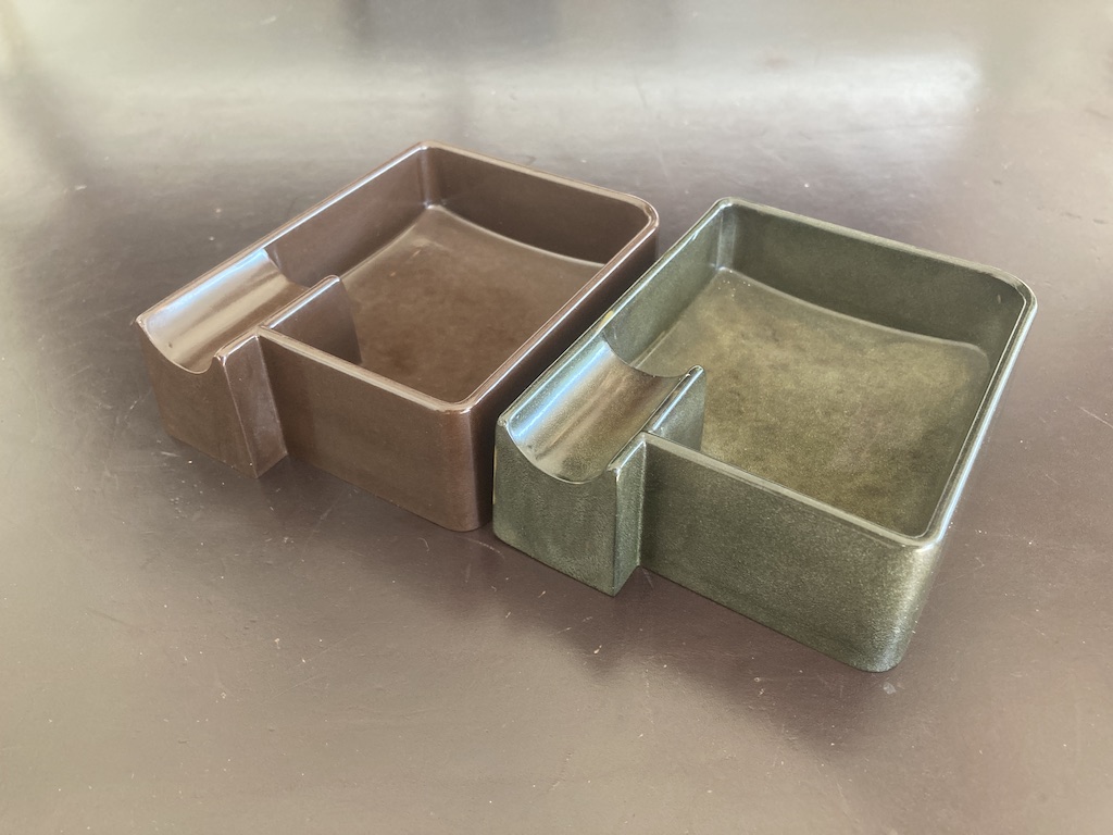
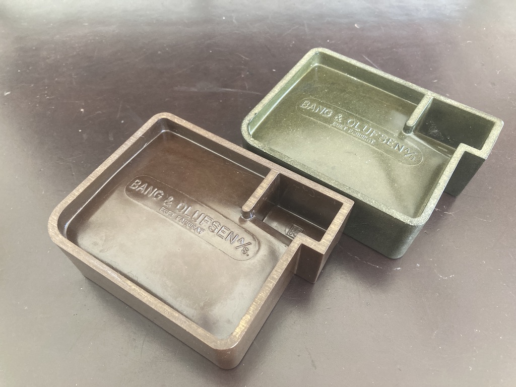
Once-upon-a-time, Bang & Olufsen had a bakelite press. I’ll probably talk about this sometime in the future, but the short version is that bakelite was an early kind of plastic that gave people a whole new way of making products with new shapes (do a search for Beolit 39 for example).
B&O used its bakelite press to make items other than radios and parts for their audio products. One example of this is the ashtrays you see in the photos below. One thing to notice is the B&O logo up on the underside of the cigar/cigarette rest.
This week, a question came in from a B&O customer about their Beovox Cona subwoofer, starting with this photograph:
The question (as it was forwarded to me, at least…) was “what does ‘Long term max power 125w’ and ‘Max noise power 60w’ mean?”
This caused me to head to our internal library here in Struer and look at an ancient kind of document called a ‘book’ that contained the information for the answer.
The first clue is at the top of the photo where it says “IEC 268-5”, which is a reference to a document from the International Electrotechnical Commission in Switzerland called
CEI/IEC 268-5 International Standard Sound System Equipment Part 5: Loudspeakers
As you can see there, we happen to have two copies in our library: the second edition from 1989 and 3.1 from 2007, so I took a look at the 1989 edition.
Long Term Max Power
This term is defined in part 18.2 of that document, where it says that it’s the “electrical power corresponding to the long term maximum input voltage.” In order to convert voltage to power, you need to know the loudspeaker’s rated impedance, which is 6 Ω, as is shown in the photograph above.
Power = Voltage2 / R
So, in order to find the Long Term Maximum Power rating of the loudspeaker, we have to do a Long Term Maximum Input Voltage test, and then a little math to convert the result to power.
The Long Term Maximum Input Voltage is defined in section 17.3 as:
“… the maximum voltage which the loudspeaker drive-unit or system can handle, without causing permanent damage, for a period of 1 min when the signal is a noise signal simulating normal programme material (according to IEC 268-1).”
“The test shall be repeated 10 times with intervals of 2 min between the application of the signal.”
So, if I do the math backwards, I can calculate that the Cona was subjected to that special noise signal with an input voltage of 27.39 V with a pattern of
1 minute of continuous noise
2 minutes of silence
repeated 10 times
After this was done, the Cona was tested again to make sure that it worked. It did.
How I did the math to figure this out:
P = V2/R
therefore sqrt(P * R) = V
sqrt(125 * 6) = 27.39 V
To do the test, the loudspeaker is placed in a room of not less than 8 m3 with controlled temperature and humidity requirements. An amplifier droves the noise signal into the loudspeaker for 100 h
Max Noise Power
The Maximum Noise Power is tested in a similar way, however, instead of delivering the signal in 1 minute bursts with 2 minute rest periods, the speaker has to play the noise continuously for 100 hours. After the 100 hours are over, then the speaker is put in a room to recover for 24 hours. After this:
“The loudspeaker may be considered to have fulfilled the requirements of this test if, at the end of the storage period, there is no significant change in the electrical, mechanical or acoustical characteristics of the loudspeaker itself compared to those stated in the data sheet for the loudspeaker type, other than a change in the resonance frequency. The acceptability of this change is subject to negotiation; it shall therefore be stated when presenting the results.”
The reason the Maximum Noise Power is lower than the Long Term Maximum Power is the 2 minute rest time in the test. It’s important to remember that a loudspeaker driver is very inefficient when it comes to converting electrical power to acoustical power, and so most of the electrical power that goes into it is just lost as heat caused by inefficiency. The 2 minute rest time allows the loudspeaker to cool down a little before the signal starts heating it up again, and therefore it can handle more power (a little more than 3 dB more – which is the same as 2 x the power) than when it’s playing continuously.
It’s been a long time (about 11 years or so…) since I wrote Part 1 in this “series”, so it’s about time that I came out with a Part 2. This one is about the ‘Maximum Sound Pressure Level (SPL)’ and the ‘Bass Capability’ values that are shown for each loudspeaker model on the Bang & Olufsen website.
Before I explain either of those numbers, we need to discuss the fact that B&O loudspeakers are fully-active. This means that all the signal processing, including simple things like the volume control and more complicated things like filtering and crossovers for the loudspeaker drivers happen in a digital signal processing (DSP) chain before the amplifiers, which are individually connected to the loudspeaker drivers. (In other words, if you see a woofer and a tweeter, then there are two amplifiers inside the loudspeaker, one for each.)
That DSP chain includes even more complicated features that help to protect the loudspeaker from abuse. This means that, even if you’re playing a signal that’s been mastered at a high level, and you’ve cranked up the volume control, the processor prevents things like:
letting the loudspeaker drivers exceed their maximum excursions
letting the amplifiers go beyond their voltage or current capabilities
letting the power supply try to deliver more current than it can to the entire system
letting the loudspeaker’s internal components get so hot that things start to melt.
(None of this means that it’s impossible to break the loudspeaker. It just means that you’d have to try a lot harder than you would with a lot of other companies’ loudspeakers.)
One important side-effect of all of those protection algorithms is that, when you play a loud signal at maximum volume, the loudspeaker will be constantly trying to protect itself. Therefore its maximum output level will vary over time, depending on the signal you’re playing and things like the temperatures of its various individual components.
This, in turn, makes it difficult to state what the “Maximum Sound Pressure Level” will be, since it will change over time with different conditions.
On the other hand, it’s necessary to give a number that states the maximum Sound Pressure Level of each loudspeaker for lots of reasons. It’s also necessary that we use the same procedure to do the measurement so that the values can be compared from loudspeaker to loudspeaker.
The method
So, how do we balance these two things? The answer is to make the measurement short enough that we show the maximum output of the loudspeakers when it’s hitting its limits without being affected by a build-up of heat. This can give you an idea of how loud a short-term signal (like the punch of a kick drum or a snare drum hit) can play: the Maximum SPL. Whatever that number is, the loudspeaker definitely can’t play louder than it (since the amplifier can’t deliver more current and the loudspeaker drivers can’t move in and out any further) but that doesn’t necessarily mean it can play at that level continuously.
The way we measure both the Maximum SPL and the Bass Capability is by placing a microphone 1 m in front of the loudspeaker, and then putting in a short ‘burst’ of 5 periods of a sinusoidal tone at a given frequency. The sound pressure level of the output is measured at the microphone’s position, we wait long enough for everything to cool down, the level of the incoming signal is increased, and then we do the measurement again. This is repeated until the output signal’s level is being automatically reduced by the loudspeaker’s protection algorithms by a pre-determined amount (-6 dB).
If we were a company that made passive loudspeakers, a normal way to do this would be to increase the level until we reached a pre-determined level of total harmonic distortion (say, 10% or 20% THD, for example). However, this won’t work for a B&O loudspeaker because the protection algorithms probably won’t allow the product to distort enough to have a usable threshold.
What’s the difference?
Generally, the method of measuring both the Maximum SPL and the Bass Capability values are the same. The only difference is the range of frequencies that are used for each.
The Bass Capability shows the maximum SPL of the loudspeaker when the input signal is a 50 Hz sinusoidal wave.*
The Maximum Sound Pressure Level is an average of the maximum SPL of the loudspeaker when it is measured using a number of sinusoidal signals ranging from 200 Hz to 2 kHz. Each frequency is measured individually, and the resulting maxima are averaged to produce a single value. (If you’re read Part 1, then the frequency range of this measurement will look familiar.)
How does this correspond to real life?
This is a difficult question to answer, since the measurement is done on-axis to (or ‘directly in front of’) the loudspeaker in the measurement room. This measurement room is different from a ‘normal’ living room, where more of the total power of the loudspeaker that’s radiated in all three dimensions is reflected back to the listening position. This is the reason why some companies list the maximum output level of their loudspeakers with two numbers: one in a ‘free field’ (a room or ‘field’ that is ‘free’ of reflections) and the other in a ‘listening room’ (which may or may not be like your listening room). You’ll probably see that the ‘listening room’ SPL is higher than the ‘free field’ SPL because the room is reflecting more energy back to the measurement microphone, if nothing else…
In other words ‘results may vary’. So, the maximum SPL of a loudspeaker in your living room may not be the same as the Maximum SPL that B&O lists on its website. Time frames are different, signals are different, and rooms are different: and all of these have significant effects on the result.
What happens when I have more than one loudspeaker?
Generally speaking, if your loudspeakers are reasonably far apart, then you can use a simple rule to calculate the maximum SPL if you add more loudspeakers.
+ 3 dB per doubling
In other words, if you have a loudspeaker that can hit 100 dB SPL, and you add a second loudspeaker, then you’ll hit 103 dB SPL. If you then add two more loudspeaker (another doubling of the total number) you’ll hit 106 dB SPL.
This rule is based on a number of assumptions:
the loudspeakers are all the same type
the loudspeakers are in the same room, but fairly far apart
the loudspeakers are all playing their maximum output levels at the same time
I’m ignoring room modes, which might make things louder or quieter, depending on the frequency that you’re playing, the placements of the loudspeakers, and the location of the listening position
we’re ignoring other protection algorithms like thermal protection
The reason that this rule is a basic one: we’re assuming that every time you double the number of speakers, you double the total power at the listening position (which is a reasonable assumption if the list of assumptions above are true). Two times the acoustic power is the same as an increase of +3 dB SPL (because 10 log10(2) = 3).
If, however, the frequency was very low, and the loudspeakers were very close together, and they were playing exactly the same signals at exactly the same time, you might make the argument that you can say that there is a +6 dB increase for every doubling of loudspeakers, because it’s their amplitudes (and not their acoustic powers) that are added.
Neither of these two basic assumptions is correct, and so the real number is probably between +3 and +6 dB per doubling of loudspeakers, and it will be different for different frequency bands and different loudspeaker separations. However, it’s best to err on the safe side.
One last thing
This should help to explain why, when you compare the Bass Capabilities and the Maximum Sound Pressure Levels of different loudspeakers, the former has much bigger differences than the latter.
For example:
Beosound Explore
< difference >
Beolab 50
Max SPL @ 1 m
91 dB SPL
26 dB
117 dB SPL
Bass capability
59 dB SPL
52 dB
111 dB SPL
The table above shows a direct comparison of two VERY different loudspeaker models using data taken directly from bang-olufsen.com on 2025 04 01. I’ve converted the numbers for the Beolab 50 to a ‘per loudspeaker’ instead of ‘per pair’ by subtracting 3 dB from the published numbers.
As you can see there:
the difference in Bass Capability between a Beosound Explore and a Beolab 50 is (111-59) = 52 dB
the difference in Max SPL between a Beosound Explore and a Beolab 50 is (117-91) = 26 dB
Speaking VERY generally, the difference in Max SPL values is less than the difference in Bass Capabilities because the difference in size and power of the drivers producing the midrange frequency band of the two loudspeakers is smaller than the difference in size and power of the woofers. In other words, there is a difference between the different differences. (I think that I got that right…)
* To get the Bass Capability measurement, it looks like I said that we do the measurement of a single 50 Hz sinusoidal tone. This isn’t really true. We do a number of measurements at different frequencies ranging from 20 Hz to 100 Hz and then calculate the equivalent value for a 50 Hz tone using some averaging.
If the loudspeaker is comprised of a single low-frequency driver in a closed cabinet, then the resulting number would be the same as if we just measured using a 50 Hz tone. However, if the loudspeaker is ported or has a passive driver with a resonant frequency in the 20 – 100 Hz range, then this method will probably produce a slightly different number than measuring only with a 50 Hz tone.
A question came to my desk this week from a customer who would like to connect a third-party streaming device to his Beolab 50s. He plans to use a USB-Audio connection and his question was “Should I control the volume of the audio signal in the streamer or in the Beolab 50s?” There are three different ways to configure these two options:
Control the volume in the streamer using its interface, and send a signal that has been volume-regulated to the Beolab 50s, which should then be set to have a start up default volume such that the maximum volume on the streamer results in a level that is as loud as the customer will ever want it to be. In order to do this, the Beolab 50s need to be set to ignore the volume information that is received on the USB-Audio connection.
Set the streamer to output an unregulated signal, and set the Beolab 50s to obey the volume information that is received on the USB-Audio connection, then use the streamer’s interface for the volume control (which would actually be happening inside the Beolab 50s).
Set the streamer to output an unregulated signal, and set the Beolab 50s to disobey the volume information that is received on the USB-Audio connection, then use the Beolab 50’s interface for the volume control (which would actually be happening inside the Beolab 50s).
Of course, one way to answer the question is “where do you want to control the volume?” For example, if it’s with a remote control for the Beolab 50s, then the answer is “use option #3”. If you’d prefer to use the streamer’s app, for example, then the answer is “use option #1 or #2”.
However, the question came to my desk because it was specifically about the technical performance of the audio signal. Which of these three options results in the highest audio “quality”? (I put the word “quality” in quotation marks because it is a loaded term, and might mean different things to different persons…)
The simplest answer without getting into any details is “it probably doesn’t matter“. However, that answer is based on a couple of assumptions that may or may not be wrong.
Hypothetically, the Beolab 50 can output an audio signal that peaks at about 122 dB SPL measured at 1 m in a free field, albeit not at all frequencies present at its output. (This is because there are some physical limitations of how far the woofers can move, which means that you can’t get 122 dB SPL at 20 Hz, for example.) The noise floor of the Beolab 50s is about 0 dB SPL measured in the same place (again, this is frequency-dependent). So, it has a total dynamic range at its output of about 122 dB.
The maximum output level is a result of a combination of the loudspeaker drivers, the amplifiers, and the power supply, however, these have all been chosen to reach their maximum outputs approximately simultaneously, so changing one of the three won’t make a big difference.
The noise floor is a result of the combination of the loudspeaker drivers’ sensitivities, the amplifiers’ noise floors, and the signal that feeds the amplifiers: the DAC outputs’ noise floors. For the purposes of this discussion, I’m sticking with a digital input, so we don’t need to worry about the noise floor of the ADC at the loudspeaker’s input.
If you have an audio signal at one of the digital inputs of the Beolab 50, and that signal is at its loudest possible level (for a sine wave, that’s 0 dB FS; or 0 dB relative to Full Scale). At Beolab 50’s maximum volume setting, this will produce a peak output level of 122 dB SPL (depending on the frequency as I mentioned above).
All digital inputs of the Beolab 50 accept at least a 24 bit word length. This means that the dynamic range of the digital input signal itself is about 6 * 24 – 3 = 141 dB. This in turn means that the hypothetical noise floor of a correctly-dithered 24-bit signal is 19 dB below the noise floor of the loudspeakers even at their maximum volume setting. (because 122 – 141 = -19)
In other words, if we assume that the streamer has a correctly-implemented gain function for its volume control, using TPDF dither implemented at the 24-bit level, then its noise floor will be 19 dB below the “natural” noise floor of the Beolab 50. Therefore, if the volume is controlled in the streamer, any artefacts will be masked by the 50s themselves.
On the other hand, the Beolab 50s volume control is done using a gain function that is performed in a 32-bit floating point calculation, which means that it has a dynamic range of 144 to 150 dB. (See this posting for an explanation and comparison of fixed point and floating point systems.) So the noise generated by the internal volume control will be somewhere between 22 and 26 dB below the “natural” noise floor of the Beolab 50.
So, (assuming my assumptions are correct) the noise floor that is produced by controlling the volume control in either the streamer or the Beolab 50s is FAR below the constant noise floor of the DAC / amplifiers.
In addition, the noise floors have roughly the same spectra (in other words, you don’t have pink noise in one case but white noise in the other; they’re all producing white noise). And since both are so far below, it really doesn’t matter. Arguing about whether the noise is 19 dB lower or 22 dB lower is a waste of good argument time, unless you paid for the four-and-a-half-hour argument instead of the five-minute one…
Important Notes
If the customer was asking about using the analogue input, then the answer MIGHT have been different.
Also, if my assumption about a 24-bit signal coming from the streamer, or that it has a correctly-implemented gain function for its volume control are incorrect, the this answer MIGHT be incorrect as well.
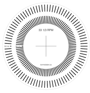
One of the things on my to-do list today was to get a Bang & Olufsen Stereopladespiller Type 42 up and running. Unfortunately, I didn’t have a stroboscopic disc for testing the speed. Since a quick search on the Internet didn’t turn up anything I liked, I decided to make my own.If you’d like to download it, it’s available here as a PDF file for A4 paper, and contains the lines for 50 Hz and 60 Hz mains. You can change the magnification to make it fit on different paper sizes, or to increase or decrease the size of the disc. If your magnification is the same in the X and Y axes, then it won’t change anything.
This meant that I had to do a little math, which goes as follows:
mains_frequency = 50 Hz (this is the rate at which the lights blink)
So, here in Denmark where we have 50 Hz mains, I needed to make a disc with a line every 4º. Since I use a Mac, I used graphic.app to do this, but any decent drawing program will do the trick.
If you want to make your own disc, and you don’t want to do the math, here are the results of the possible mains frequencies and revolution speeds
RPM
50 Hz
60 Hz
16
1.92
1.60
33 1/3
4.00
3.3333…
45
5.3999…
4.50
78
9.36
7.80
For anyone who knows a thing or two about the Type 42… then I’m already ahead of you. I know that the lines are built into the turntable mat itself. However, I was working in pretty bright daylight, and so I needed more contrast on the lines to be able to see the interference from the lighting. And besides, it was fun as a little light recreational math.
The June 1980 issue of Audio Magazine contains an article written by Subir K. Pramanik called “Understanding Tonearms”. This is a must-read tutorial for anyone who is interested in the design and behaviour of radial tonearms.
One of the things Pram talked about in that article concerned the already well-known relationship between tonearm geometry, its mounting position on the turntable, and the tracking error (the angular difference between the tangent to the groove and the cantilever axis – or the rotation of the stylus with respect to the groove). Since the tracking error is partly responsible for distortion of the audio signal, the goal is to minimise it as much as possible. However, without a linear-tracking system (or an infinitely long tonearm), it’s impossible to have a tracking error of 0º across the entire surface of a vinyl record.
One thing that is mentioned in the article is that “Small errors in the mounting distance from the centre of the platter … can make comparatively large differences in angular error” So I thought that I’d do a little math to find out this relationship.
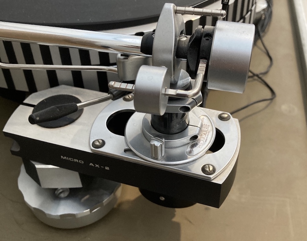
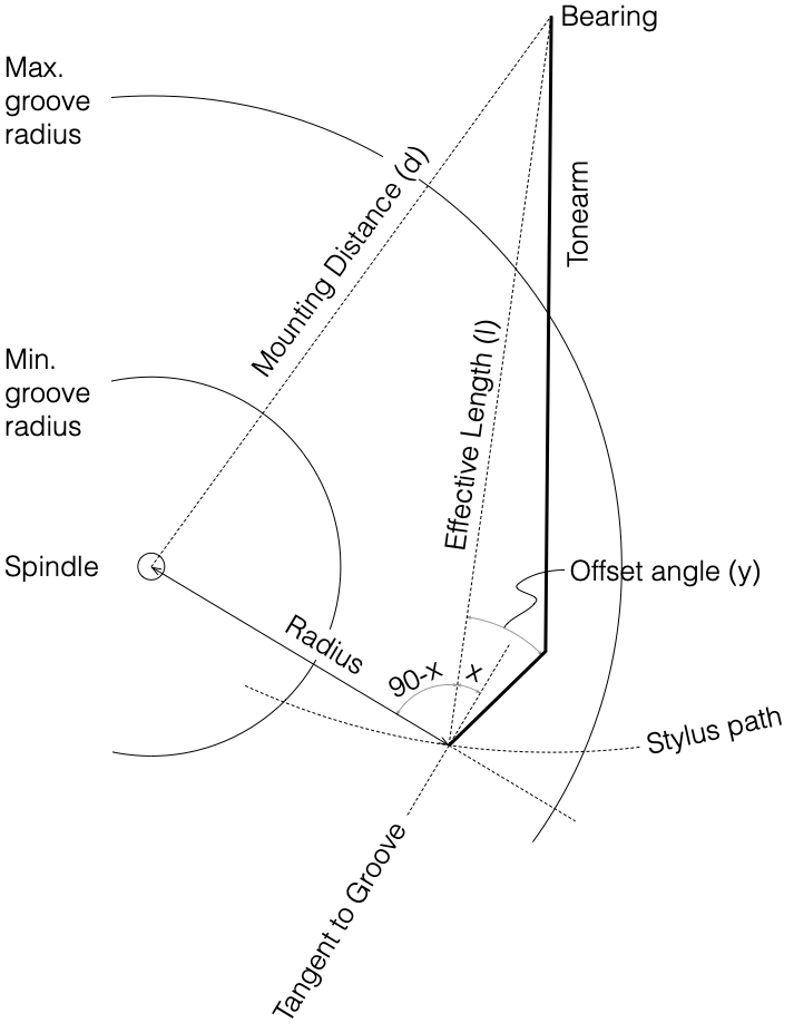
The article contains the diagram shown below, showing the information required to do the calculations we’re interested in. In a high-end turntable, the Mounting Distance (d) can be varied, since the location of the tonearm’s bearing (the location of the pivot point) is adjustable, as can be seen in the photo above of an SME tonearm on a Micro Seiki turntable.
The tonearm’s Effective Length (l) and Offset Angle (y) are decided by the manufacturer (assuming that the pickup cartridge is mounted correctly). The Minimum and Maximum groove radius are set by international standards (I’ve rounded these to 60 mm and 149 mm respectively). The Radius (r) is the distance from the centre of the LP (the spindle) to the stylus at any given moment when playing the record.
In a perfect world, the tracking error would be 0º at all locations on the record (for all values of r from the Maximum to the Minimum groove radii) which would make the cantilever align with the tangent to the groove. However, since the tonearm rotates around the bearing, the tracking error is actually the angle x (in the diagram above) subtracted from the offset angle. “X” can be calculated using the equation:
x = asin ((l2 + r2 – d2) / (2 l r))
So the tracking error is
Tracking Error = y – asin ((l2 + r2 – d2) / (2 l r))
Just as one example, I used the dimensions of a well-known tonearm as follows:
Effective Length (l) : 233.20 mm
Mounting Distance (d) : 215.50 mm
Offset angle (y) : 23.63º
Then the question is, if I make an error in the Mounting Distance, what is the effect on the Tracking Error? The result is below.
If we take the manufacturer’s recommendation of d = 215.4 mm as the reference, and then look at the change in that Tracking Error by mounting the bearing at the incorrect distance in increments of 0.2 mm, then we get the plot below.
So, as you can see there, a 0.2 mm error in the location of the tonearm bearing (which, in my opinion, is a very small error…) results in a tracking error difference of about 0.2º at the minimum groove radius.
If I increase the error to increments of 1 mm (± 5mm) then we get similar plots, but with correspondingly increased tracking error.
If you go back and take a look at the equation above, you can see that the change in the tracking error is constant with the Offset Angle (unlike its relationship with an error in the location of the tonearm bearing, which results in a tracking error that is NOT constant). This means that if you mount your pickup on the tonearm head shell with a slight error in its angle, then this angular error is added to the tracking error as a constant value, regardless of the location of the stylus on the surface of the vinyl, as shown below.