Today was spent doing a bunch of small jobs while I wait for some replacement parts to arrive.
For starters, I found two needles under the hinge on the bottom half of the case. They’ll come in handy later!
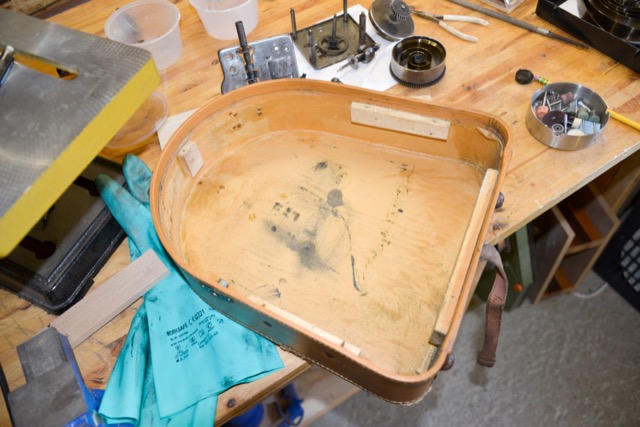
The interior of the case, showing the four wood blocks to which the top screws on. Funnily, these are made of three different types of wood: pine, birch, and beech. I suspect that this was not strategic – but just a question of using whatever was on-hand. The lining is a waxy paper – the black stains are grease that has dripped down from the drive mechanism.
The four pieces of wood are two different heights from the top edge of the casing, although I suspect that this would have been custom-fitted. They’re attached to the outer casing using either tacks (the largest piece on the right) or split rivets that were bent over to lock the wood in place. The wood parts are not glued onto the case. All of the rivet and tack heads of these are badly rusted – so they’re coming out…
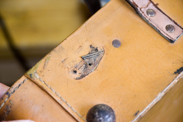
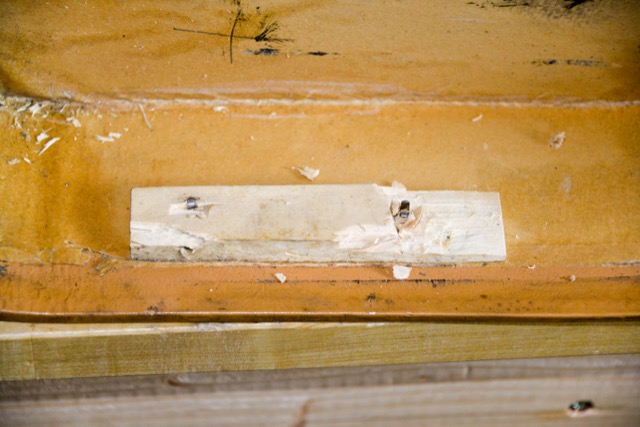
One of the split rivets after the wood has been removed. The wood did not survive the removal process. The hole on the far left is the opening for the crank.
The wood in the process of removal. I’ll just make new blocks to replace these…
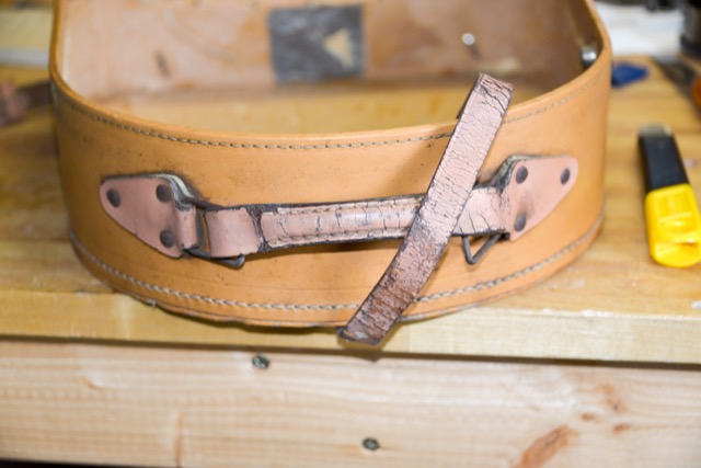
The handle and strap are a different colour than the case, and are in quite bad shape. In addition, the hardware is badly rusted. This will all get replaced with new parts.
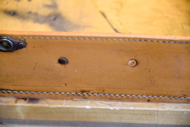
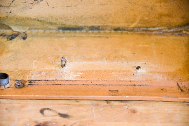
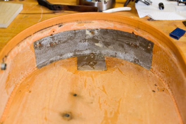
The handle and strap are attached with the same split rivets, but bent around a canvas material that’s glued to the inside of the case, as can be seen in the photo above. The canvas is the dark square and rectangle. This canvas can’t be seen normally, because it’s covered by the wax paper. I peeled this off, because I’ll be replacing it with something a little more sturdy.
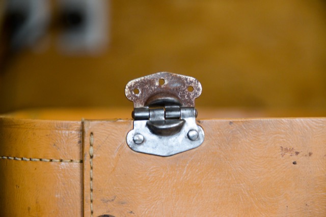
The rust on the exterior metal parts was cleaned up with a small wire brush on my Dremel tool. The before-and-after can be seen above. This took some time so as to not slip and carve into the case covering.
I used Simichrome to polish the metal tonarm. This appears to be plated brass. I’m not going to take apart the reproducer (the black part that holds the needle and contains the diaphragm).
If you look carefully, you’ll see a small set screw sticking out of the half of the tonearm on the right. That’s used to stop the front portion of the tonearm from making a full rotation when it’s swivelled back and forth onto the record, by hitting the portion of the threaded pipe that can be seen below.
So, if you’re dismantling the tonearm, remember to back off the set screw before separating the two parts.
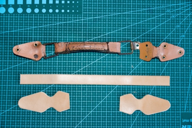
I also started the leather work to make a new handle and strap. The replacement hardware and dye were ordered from laederiet.dk, near Aarhus (which is where I buy all my leather supplies).
Apart from all of that, I washed the exterior of the case with dish soap and a soft cloth – not too wet because there are some places where the covering is worn through and I don’t want water getting in there.
I also sprayed the interior fabric (maybe taffeta?) with an enzyme spray and rubbed it gently to remove some of the stains. Too much rubbing frays the fabric, so I had to be gentle…
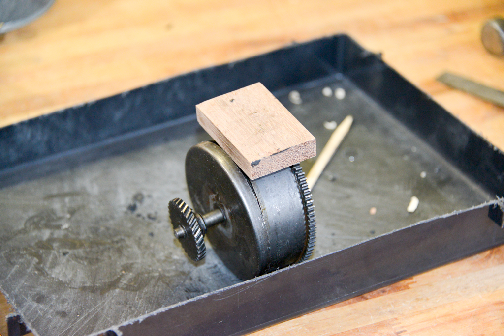
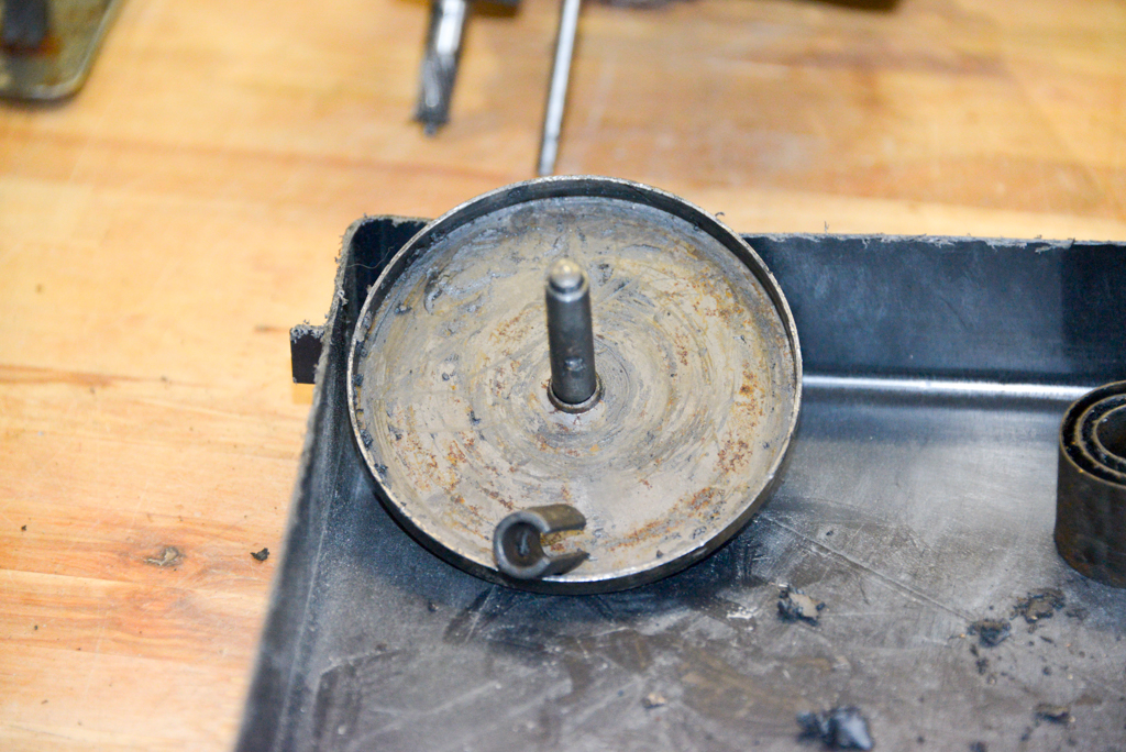
The cap comes off the mainspring barrel by tapping it with a hammer while holding onto the barrel itself. The inside shaft was already able to move up and down, so it was obvious it was no longer attached to the mainspring itself. The block of wood is used to prevent the hammer from damaging the cap edge. You hit the wood instead of the metal.
With the cap off, it’s easy to see that the mainspring is unfortunately broken. So, there are two options: Try to drill a new hole at the end of the remaining spring. This will mean heating it up to soften the steel a little… OR Try to replace it with a new spring.
A shot of the axle and the broken end of the spring. There’s a hole at the end of that spring that is caught by the hook that you can see on the axle. That hook is actually part of a sleeve that slides off the axle itself, as can be seen below.
The gap in the sleeve sits on either side of a pin that sticks out from the axle. This prevents it from rotating.
The rest of the mainspring is out of the barrel. This has to be done carefully to prevent it jumping out and either breaking something or punching a hole in me. One way to do this is to hold onto it on both sides of the barrel with two hands, and lifting one side of the spring out. This will push its way out until it gets stopped by your other hand, then you just alternate hands to let it out 180 degrees at a time. The only thing to be careful of at the end is to avoid bending the spring, since it will be caught on the pin on the inside of the barrel.
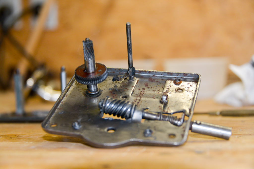
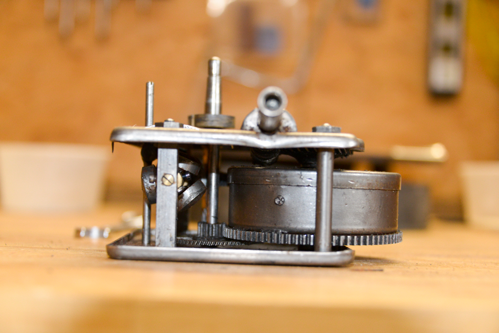
The bottom plate and the centrifugal speed regulator. The axle with the toothed gear just lifts out.
A close-up of the speed regulator and the clutch wheel, still covered in grease. Note that the pins on the end of that axle sit in brass bearings that are just holes drilled into pins. However, the holes are not centred. So, if you back off the set screws on the “front” of the vertical post, you can rotate the brass pins to change the height of the axle. Only the set screws are threaded.
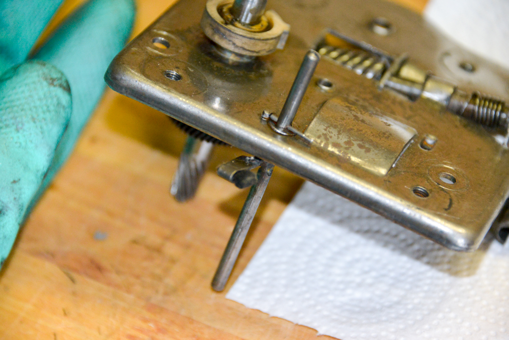
The underside of the top plate. The spring that can be seen there is used to prevent the screw from rotating counter-clockwise. (Clockwise rotation loosens the spring. Counter-clockwise tightens it.) The portion that sticks out on the right is the part that the handle screws into from the outside. So, you can screw it on, tighten the spring, but then, when you reverse the rotation of the handle, it just unscrews because the rotation is stoppped by that spring grabbing the axle.
Another view of the same part. Notice the small cotten pad that sticks out of the arm connected to the tall rod in the back. That’s the part that pushes against the clutch wheel to slow things down.
The top of that same part. There’s still plenty of old grease in the worm gear… I didn’t take anything apart more than this. All of the degreasing was done in the state the you see in the photos above.
Degreasing started by just scraping off the goop with small wooden picks that I made from scraps I had lying around. The next step was to spray on WD-40 degreaser and start wiping things down with paper towels and a stiff plastic brush. That procedure was repeated until things were looking clean, but not necessarily shiny.
The photo above shows most of the bits and pieces degreased and cleaned up.
One last close-up of the cotton pad that is used for the speed regulator.
Back to the spring… I decided to not try to heat the steel, bend it to a smaller radius, and drill a new hole. Instead, I remembered that I might have some lying around. About a year or two ago, I bought a collection of tools and leftover parts from a guy who had planned to try watch and clock repair as a retirement hobby. He had bought the collection from a retired watchmaker.
In that collection, there were some old mainsprings for mantle clocks. Time to dig those out…
First thing is to measure the Telefunken’s mainspring. Turns out its roughly 23 mm wide, 0.5 mm thick, about 3.5 m long (this is just a rough estimate based on pulling it as straight as I could for as far as I could…) and the barrel interior is 78 mm in diameter. This means that I’m looking for a mainspring that’s 23 x 0.5 x 3500 x 78 – give or take…
A box of old clock mainsprings that I happened to have lying around…
I selected the spring that best matched, based on the width, and thickness and unpacked it. This is a delicate matter that involves holding the spring in a thickly gloved hand, cutting the wire, and then slowly releasing it under a towel. That way, if it does jump, you’ll only get hit in the face with a towel…
Sadly, the spring that I had on hand was too short. So, I’ve ordered one from lindholds.dk. The one that’s coming is also not as long as the original, but hopefully, it’ll do the trick.
Tomorrow: Greasing and reassambling as much of the drivetrain as I can, and starting to clean up the case.
I recently bought a well-used Telefunken Lido portable gramophone. It’s in reasonable shape, but it certainly needs quite a lot of repair and/or restoration. For starters, it doesn’t work – probably because the drive spring is either broken or disonnected inside the barrel.
The plan is to get as much fixed on it this weekend… however, that plan may change as the work progresses.
I’ve already made use of this page, this page, and this video to get ready for the project (including learning from the mistakes of others…) My documentation might be of similar use to others – in addition to providing some info on how gramophones worked…
The lido, as-is before I start…
The platter just lifts off.
The diagonal arm is the speed control that adjusts a clutch mechanism that can be seen in photos below. The needle and membrane are locked in the “travel” position, which sits them down into the mouth of the horn (the dark rectangular area at the “back”).
The first step was to unscrew the locking lid stay on the left side of the horn opening. The next step is to unscrew the lid hinges from the main case. Both the lid stay and the hinges are riveted to the lid, so they stay on.
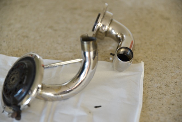
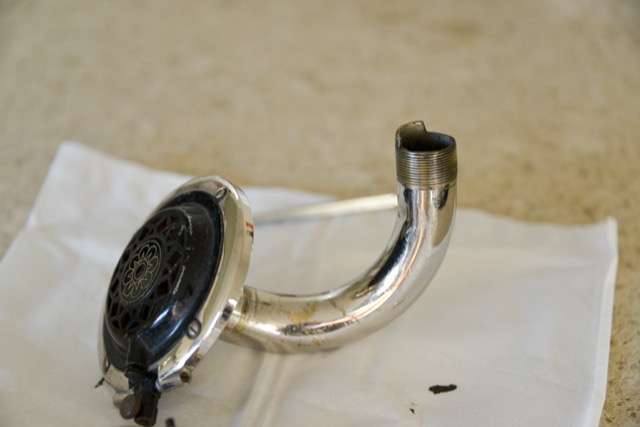
The next step was to remove the three screws that hold the pipe + membrane + needle assembly onto the wooden top plate in the top right corner. After these have been removed, it all just lifts off.
Next is to remove the 5 small screws around the outer edge of the wood top plate. These hold the entire assembly into the bottom part of the case.
The next step is to disassemble the mechanism from the wooden top plate. In order to do this, the speed regulation arm has to be disconnected from the pin that connects it to the clutch underneath. This is done by loosening at least one of the two set screws that grab the pin.
The photo above shows the control arm after separating it from the pin that goes down into the mechanism.
Once this is done, there are four large screws the have to come out. Those are the four holes near the right-hand yellow “Fona” sticker.
In order to remote the drive mechanism, it has to be gently angled to slide it out without the spindle hitting the wood, and snaking it out around the horn.
The mechanism after removal.
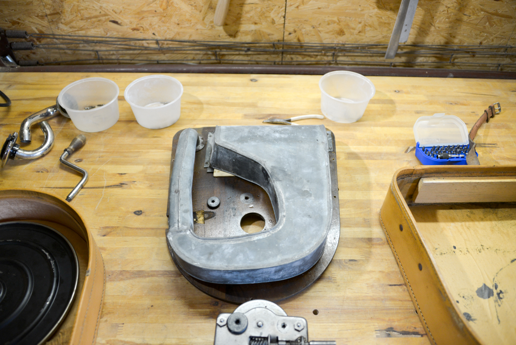
The underside of the wooden plate, showing the entire horn. This is probably made of lead by the looks of things…
The two vertical rods are the main spindle (on the left) and the clutch control (on the left). Turning the clutch control pushes a soft pad against the vertical clutch wheel that can be seen on the same axle as the centrifugal speed regulator weights.
There are four 11 mm hex nuts holding the top plate of the mechanism to the four posts. First, the rubber washers needed to be removed using a knife to separate them from the top plate. Then the four nuts are loosened and the top plate can be lifted off. This will take the clutch rod and the main spindle with it.
The photo above shows the bottom plate with the speed regulator and the spring barrel.
The two last photos, above, show the underside of the top plate, holding the main spindle on the left, the clutch rod in the middle, and the screw entry for the winding handle.
That’s it so far. Tomorrow will probably be spent disassembling the spring barrel and seeing whether it’s fixable. Then de-greasing and cleanup of the drive mechanism, re-greasing and re-assembly.
As I’ve talked about in a previous posting, when a reciprocal peak/dip filter says “Q”, there’s no knowing what it might mean, because there are at least 7 different definitions of Q (3 for boosts and 4 for dips).
For many people, this doesn’t really matter. If you’re just playing with an EQ to make things sound better right now, then the values on the display really don’t matter: it’s the sound that counts.
If you’re like me, you need to be able to navigate between different pieces of software and hardware, and to get the same EQ response from them, then you’ll also need to know firstly that you can’t trust the display, and secondly, how to “translate” from device to device when necessary.
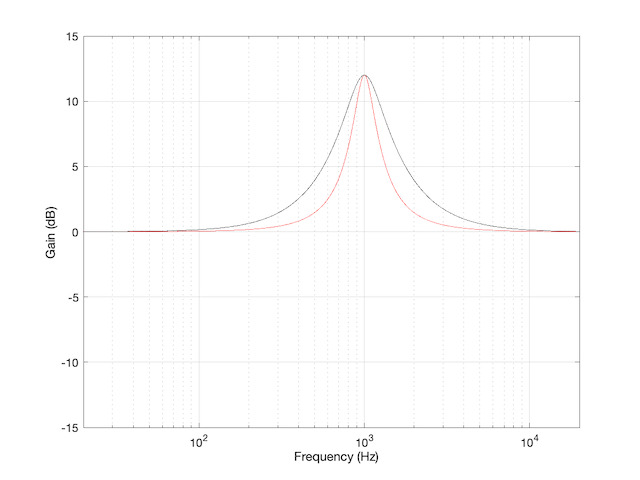
For example, take a look at Figure 1
Figure 1: The magnitude response of two peaking filters, both with Fc=1 kHz, Gain = +12 dB, Q = 2
This shows two magnitude responses, however, these are the measurements of two equalisers with identical settings: Fc = 1 kHz, Gain = +12 dB, Q = 2.
The black curve shows the response of an equaliser that uses the -3 dB points to define the bandwidth of the filter, and therefore the Q is based on 1/(2 zeta). The red curve shows the response of an equaliser that uses the mid-point (in this case, +6 dB because the Gain is +12 dB) to define the bandwidth of the filter.
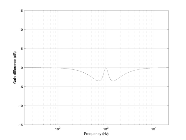
The difference between these two plots is shown below in Figure 2.
Figure 2: The difference between the two curves in Figure 1.
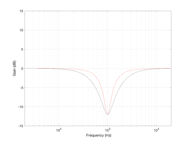
We’d have a similar problem if we were cutting instead of boosting, as shown in Figure 3.
Figure 3: The magnitude response of two peaking filters, both with Fc=1 kHz, Gain = -12 dB, Q = 2
You have to think upside down in this case, because the 1/(2 zeta) filter is actually using the 3 dB UP points to measure bandwidth; but we’ll ignore that and move on.
If you need to translate between the two systems shown above, there’s a pretty easy way to do it.
I’ll assume that you are implementing your filter using the mid-point definition of the bandwidth, so you need to convert into that system rather than out of it. (I’m making this assumption because it’s the one that Robert Bristow-Johnson used in his Audio Cookbook, which was freely copy-and-pasteable, which means that you find it everywhere these days.) Get the parameters from the filter you want to copy.
We’ll call these parameters Fc (for centre frequency, in Hz), (Gain in dB), and . I’m calling it because it’s a Q based on 1/(2 zeta) and we’ll need to keep it separate from our other Q, which I’ll call (for Robert Bristow-Johnson).
Convert the gain into linear.
Then do the following:
IF
ELSEIF
ELSE your filter isn’t doing anything because
END
Example 1
If you have a -3 dB-based filter with the following parameters:
and you want to implement that using the Bristow-Johnson equations, then you’ll have to use the following parameters:
Example 2
If you have a -3 dB-based filter with the following parameters:
and you want to implement that using the Bristow-Johnson equations, then you’ll have to use the following parameters:
Two Extra Things…
If the filter that you’re translating FROM is based on Andy Moorer’s design (which is based on the gain mid-point if the gain is within the ±6 dB range, but based on the 3 dB points if it’s outside that), then you’ll have to write your own IF/THEN statements.
If you’re implementing a filter that was specified for RBJ’s equations in a system that’s based on 1/(2 zeta), then you’re probably smart enough to figure out how to do the above in reverse.
One additional addendum
IF you don’t like IF/THEN statements for some reason or another (code optimisation, for example)
THEN you could do it this way instead:
What I’ve done there is to fold the decibel-to-linear conversion into the equation. I’ve also converted the gain in dB to an absolute value before converting to linear. That way, it’s always positive, so you always divide.
These days, I’m spending a lot of time wrapping my head around the relationship between the frequency and the time responses of filters. In doing so, I’m digging into the concept of “Q”, of course. As a result, I’m reading my old books and some Internet sites, and I’m frequently presented with something like the following:
That, of course, is from the Wikipedia entry on “Q”.
However, in the Bell Telephone System Technical Publication – Monograph 2491, called “The Story of Q” by Estill I. Green ( published in the American Scientist, Vol 43, pp 584-594, in October 1955), it states:
“For a time, Johnson* designated the ratio of reactance to effective resistance of a coil by the symbol K. It was in 1920, while working the practical application of the wave filter which G. A. Campbell had invented some years before, that he for the first time employed the symbol Q for his parameter. His reason for choosing Q was quite simple. He says that it did not stand for ‘quality factor’ or anything else, but since the other letters of the alphabet had already been pre-empted for other purposes, Q was all he had left.”
So, if we’re going to be pedantic (which I love to be) there are two errors on that Wikipedia page. Firstly, Q does not stand for Quality. Secondly, it’s not the “Q factor”, it’s just the “Q”.
As an aside, that monograph is not only informative, it’s fun to read (depending, of course, on your definition of “fun”). For example, near the end of the paper, Green applies Q to rotating bodies (which is not a surprise, since an audio-wave oscillation is just a rotation represented in two dimensions). In that section, he points out that the rotation of the earth is slowing down due, in part, to tidal friction. Consequently, the length of a day is increasing at a rate of 0.00164 second per century, which would make the Q of the rotation of the earth equal to about 10,000,000,000,000 (10^13).
* K.S. Johnson worked in the Western Electric Company’s Engineering Department, which became Bell Telephone Laboratories in 1925.
This week, I was asked a very specific question about connecting an older pair of Beolab loudspeakers to a stereo preamp from another company. Specifically, the owner was wondering why the pairing wasn’t working out too well – and he had already had a theory that the problem had something to do with the sensitivity of his Beolab 9’s.
To be honest, I don’t really know what the problem is with this specific customer’s system – but I made a guess and I figured that the answer might be useful to someone else…
For starters, let’s do some sensitivity training. More accurately, let’s talk about loudspeaker sensitivity. This is a measure of how loud the acoustical output of a loudspeaker is for a given electrical input. Since Beolab loudspeakers are active (meaning, in part, that the amplifiers are built-in) this means that we are talking about an output level in dB SPL for a given input in volts.
For most Beolab loudspeakers, you will get an output of 88 dB SPL for an input of 125 mV RMS if you measure the loudspeaker on-axis in a free field. There are some exceptions to this, most notably Beolab 1, 9, and 5, which will produce 91 dB SPL instead.
So, this tells us how loud the loudspeaker will be for a given input. But my guess is that this had nothing to do with the customer’s problem.
Most customers connect their Beolab loudspeakers to a Bang & Olufsen source using something called a “Power Link” connection. This is a little bundle of wires that contains two audio channels (probably left and right) as well as a data channel (telling the loudspeaker things like the volume setting, for example) and a 5 V DC on/off signal.
Power Link is specified to have a maximum level of 6.5 V RMS, assuming that the signal is a sine wave. This means that a device with a Power Link output can produce no more than 9.2 V Peak. It also means that a device with a Power Link input (like a Beolab loudspeaker) will clip (and therefore distort) at its input if you feed it with more than 9.2 V Peak.
(If you do some math, you can calculate that 20*log10(6.5 V RMS / 125 mV RMS) = 34.3 dB. Therefore, if a Beolab 9 loudspeaker will produce 91 dB SPL with a 125 mV RMS input, then it should produce 91+34.3 dB = 125.3 dB SPL for a maximum accepted input of 6.5 V RMS. Of course, this is not possible – but it’s because the loudspeaker is limited by its drivers, amplifiers, and power supply – not the input maximum input level.)
Back to the question: The customer in question mentioned his stereo preamp’s brand and model number. A little Duck-Duck-Go-ing helped me to find the manual for that particular device, and in the back of that document, I found out that the maximum output level of the preamp was 29 V RMS – which is a lot…
So, the problem is very likely that his preamp is overloading the input stages of the Beolab 9. So, if he turns the volume knob on the preamp up to maximum, and he’s playing a tune that is mastered to be loud on the playback media, then the Beolab 9’s input will be clipped. Changing the sensitivity of the loudspeaker could make it quieter – but it will still be clipped… So the distortion won’t get better – everything will just get quieter.
There are some different solutions to this problem. The easiest one is to not turn up the volume on the preamp – but this is not the best solution, because it means that he’s not using the full dynamic range of the preamp (probably), and therefore that the noise from the preamp is higher in level than it needs to be at the input of the Beolab 9.
There is, however, a very cheap and simple solution, and that is to attenuate the output of the preamp so that when it is set to its maximum output level, it is just hitting the maximum input level of the loudspeaker’s input.
How do we do this? the first question is to find out what the attenuation should be.
Maximum output level = 29.0 V RMS
Maximum input level = 6.5 V RMS
20*log10 (6.5 / 29.0) = -12.99 dB
This is the same as a linear gain of 0.2241.
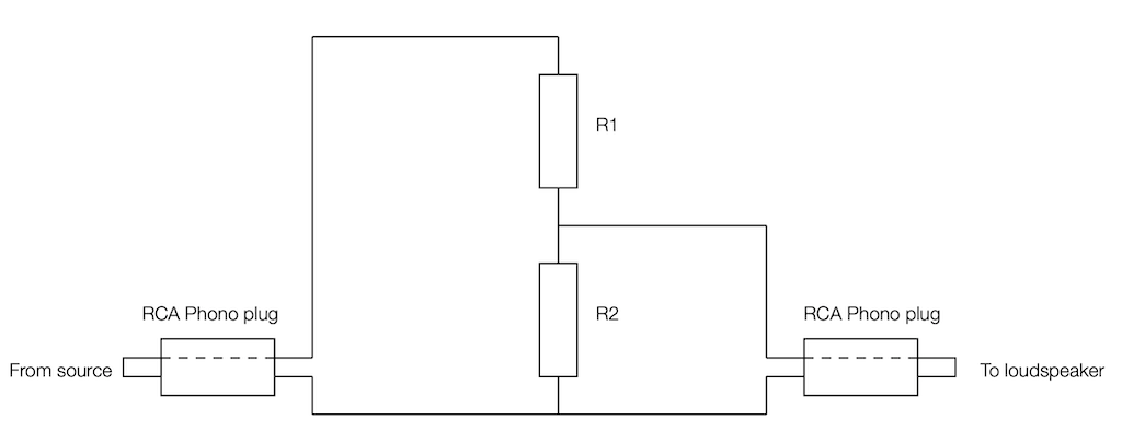
Now we’re going to build a voltage divider. This is device made of two resistors, placed in series (end-to-end) and connected to the output of the source. The point where the two resistors connect together is used as the output to the loudspeaker, resulting in a schematic as shown below.
As you can probably see in the schematic, the grounds of the two devices (which are connected to the exterior casings of the RCA Phono plugs) are connected together. As the voltage on the pin of the source goes up and down, the voltage on the pin of the loudspeaker also goes up and down – but by less. How much less is determined by the values of the resistors.
For example, if the resistors are equal (R1 = R2) then the output will be half of the input. If R2 is one tenth of the total of R1+R2, then the output will be one tenth of the input. You can calculate this gain yourself with a simple equation:
Linear Gain = R2 / (R1 + R2)
and
Gain in dB = 20 * log10 (Linear Gain)
So, for example, if R1 = 8,000 Ω and R2 = 2,000 Ω, then the gain will be
2000 / (8000 + 2000) = 0.2
which is equal to 20*log10 (0.2) -13.98 dB.
Unfortunately, if you want to do this with only two resistors, you can’t be too choosy about their resistances. There are standard resistor values, and you’ll have to pick from that list.
Also, it’s a good “rule of thumb” to try and keep the resistance “seen” by the source around 10,000 Ω (or 10 kΩ) – just to keep it happy. If you make the value too low, then you will be asking for it to deliver too much current (and its maximum output level will drop). If you make it too high, you might create and antenna and result in some extra noise…
So, I want to make R1 +R2 about 10,000 Ω, and I want R2 / (R1+R2) to be about 0.2241 (because I’m trying to convert 29 V RMS to 6.5 V RMS). So, I go to a list of standard resistor values like this one and I start trying to simultaneously fulfill those two requirements.
After some trial and error, I find out that if I make R1 = 8.2 kΩ and R2 = 2.4 kΩ, I can come pretty close.
2400 / (8200 + 2400) = 0.2264 = -12.902
close enough. Now I just need to get a soldering iron and a bit of wire, and put it all together…
The details…
However, if you clicked on that list of standard resistor values, you might notice that it says ±5% at the top of the table. This is normal. If you go to your local resistor store and you buy a 1 kΩ resistor – it probably won’t be exactly 1,000.000000000 Ω. But it will be close. If you buy from the ±5% stack, then any resistor in that bunch will be within 5% of the stated value. So, for a 1 kΩ resistor ±5%, it will be somewhere between 950 Ω and 1050 Ω.
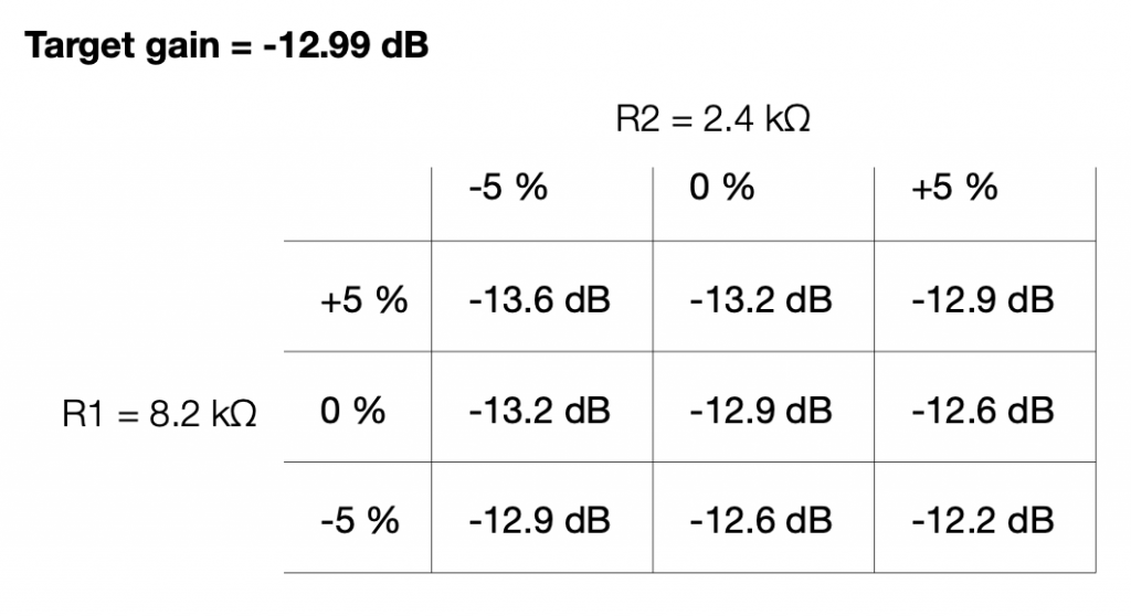
So, then the question is, for the resistors that I just picked, how bad can it get, and is that good enough?
Well… this can be calculated. I just put in the worst-case values for my two resistors into the math, and do it over and over until I get all the possible answers. This would look like this:
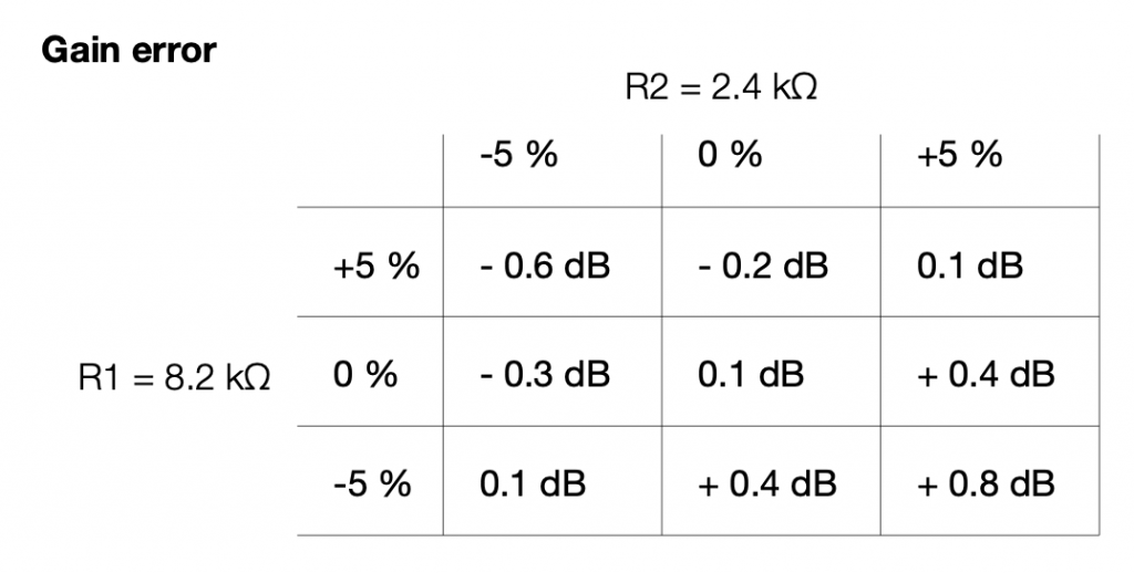
If we look at this in terms of how far away we are from the target – the gain error, then it looks like this:
So, if we randomly choose resistors out of the bag, the worst that can happen is that we will be 0.6 dB below the target or 0.8 dB above the target.
This means that, if we’re not careful, and we’re unlucky, then we can get a mismatch between the two channels of 1.4 dB (assuming that one channel was a worst-case low and the other is a worst-case high). This is enough to be audible as about a 15% shift towards the louder loudspeaker, which is probably not acceptable.
So, the moral of the story is that you should measure your resistors before soldering them into the circuit.
Note, however, that it’s not necessary to make the gains perfect to improve the imaging. You just need to make them equal in the two channels for that…
Speaking Passively
The circuit I show above is called a “passive” circuit. This means that it doesn’t require any external power source (like a battery or a power supply) to work. However, it also means that it can’t make things louder – no matter what resistor values you choose, the output will always be less than the input.
There are lots of reasons why this is a useful little circuit. It’s cheap, it’s easy to make, it’s small (you could hide it inside one of the RCA connectors), and it will prevent you from overloading the input of the downstream device (in this case, a loudspeaker). Not only that, but it will also attenuate the noise generated by the source – so not only will the customer’s system no longer clip, it will also (probably) have a lower noise floor.












 (Gain in dB), and
  . I’m calling it
  (for Robert Bristow-Johnson).
![\[G_{lin} = 10^\frac{G_{dB}}{20}\]](https://www.tonmeister.ca/wordpress/wp-content/ql-cache/quicklatex.com-5da79ddd7eef7bebd2ff0a8cb915d15f_l3.png "Rendered by QuickLaTeX.com")

![\[Q_{rbj} = \frac {Q_{z}} {\sqrt{ G_{lin}}}\]](https://www.tonmeister.ca/wordpress/wp-content/ql-cache/quicklatex.com-0d9e5308a56434a6f41d2ffd76826fd7_l3.png "Rendered by QuickLaTeX.com")

![\[Q_{rbj} = Q_{z} * \sqrt{ G_{lin}}\]](https://www.tonmeister.ca/wordpress/wp-content/ql-cache/quicklatex.com-7701b5c28ecc1e78b2213e6bcfb2cbdf_l3.png "Rendered by QuickLaTeX.com")




![\[Q_{rbj} = \frac {2} {\sqrt{ 3.9811}} = 1.0024\]](https://www.tonmeister.ca/wordpress/wp-content/ql-cache/quicklatex.com-e54e30d0230089601b1f302f89c444a7_l3.png "Rendered by QuickLaTeX.com")



![\[Q_{rbj} = 2 * \sqrt{ 0.3548} = 2.3826\]](https://www.tonmeister.ca/wordpress/wp-content/ql-cache/quicklatex.com-73ba935617322fb87a09fff66729f141_l3.png "Rendered by QuickLaTeX.com")
![\[Q_{rbj} = \frac{Q_{z} }{ \sqrt{10^\frac{\lvert G_{dB} \rvert }{20}}}\]](https://www.tonmeister.ca/wordpress/wp-content/ql-cache/quicklatex.com-9d5c89c7773d38d1f6d2801064f2fd8b_l3.png "Rendered by QuickLaTeX.com")