Time to get inside and find out what’s wrong…

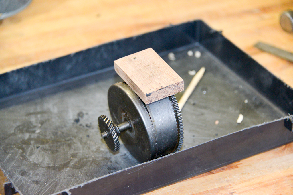
The cap comes off the mainspring barrel by tapping it with a hammer while holding onto the barrel itself. The inside shaft was already able to move up and down, so it was obvious it was no longer attached to the mainspring itself. The block of wood is used to prevent the hammer from damaging the cap edge. You hit the wood instead of the metal.

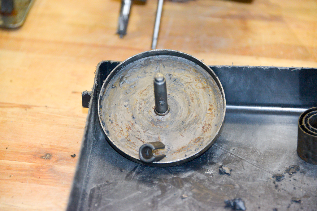
With the cap off, it’s easy to see that the mainspring is unfortunately broken. So, there are two options: Try to drill a new hole at the end of the remaining spring. This will mean heating it up to soften the steel a little… OR Try to replace it with a new spring.

A shot of the axle and the broken end of the spring. There’s a hole at the end of that spring that is caught by the hook that you can see on the axle. That hook is actually part of a sleeve that slides off the axle itself, as can be seen below.

The gap in the sleeve sits on either side of a pin that sticks out from the axle. This prevents it from rotating.

The rest of the mainspring is out of the barrel. This has to be done carefully to prevent it jumping out and either breaking something or punching a hole in me. One way to do this is to hold onto it on both sides of the barrel with two hands, and lifting one side of the spring out. This will push its way out until it gets stopped by your other hand, then you just alternate hands to let it out 180 degrees at a time. The only thing to be careful of at the end is to avoid bending the spring, since it will be caught on the pin on the inside of the barrel.

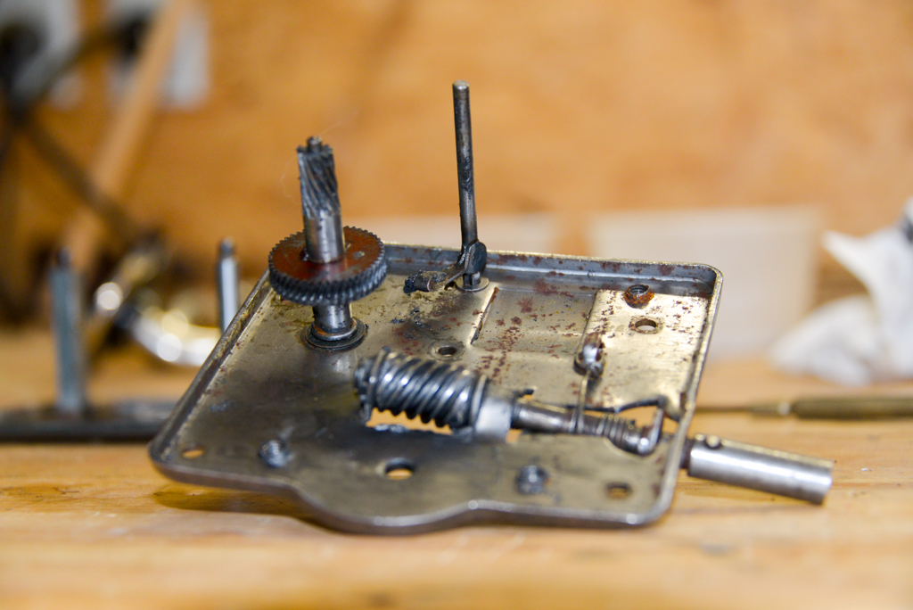
The bottom plate and the centrifugal speed regulator. The axle with the toothed gear just lifts out.

A close-up of the speed regulator and the clutch wheel, still covered in grease. Note that the pins on the end of that axle sit in brass bearings that are just holes drilled into pins. However, the holes are not centred. So, if you back off the set screws on the “front” of the vertical post, you can rotate the brass pins to change the height of the axle. Only the set screws are threaded.

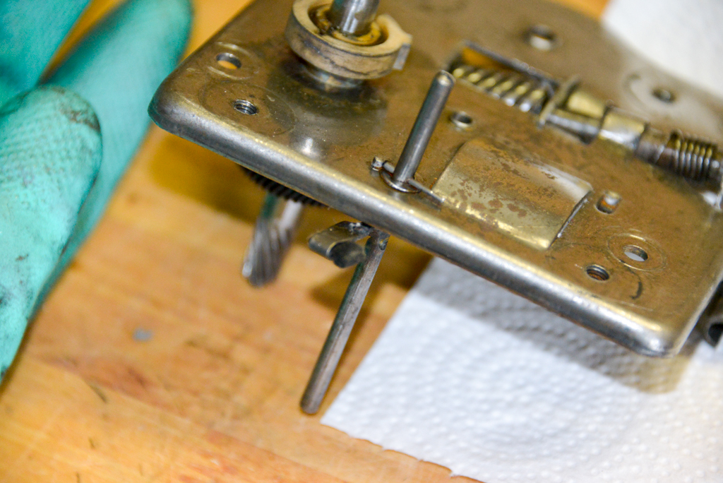
The underside of the top plate. The spring that can be seen there is used to prevent the screw from rotating counter-clockwise. (Clockwise rotation loosens the spring. Counter-clockwise tightens it.) The portion that sticks out on the right is the part that the handle screws into from the outside. So, you can screw it on, tighten the spring, but then, when you reverse the rotation of the handle, it just unscrews because the rotation is stoppped by that spring grabbing the axle.

Another view of the same part. Notice the small cotten pad that sticks out of the arm connected to the tall rod in the back. That’s the part that pushes against the clutch wheel to slow things down.

The top of that same part. There’s still plenty of old grease in the worm gear… I didn’t take anything apart more than this. All of the degreasing was done in the state the you see in the photos above.
Degreasing started by just scraping off the goop with small wooden picks that I made from scraps I had lying around. The next step was to spray on WD-40 degreaser and start wiping things down with paper towels and a stiff plastic brush. That procedure was repeated until things were looking clean, but not necessarily shiny.

The photo above shows most of the bits and pieces degreased and cleaned up.

One last close-up of the cotton pad that is used for the speed regulator.
Back to the spring… I decided to not try to heat the steel, bend it to a smaller radius, and drill a new hole. Instead, I remembered that I might have some lying around. About a year or two ago, I bought a collection of tools and leftover parts from a guy who had planned to try watch and clock repair as a retirement hobby. He had bought the collection from a retired watchmaker.
In that collection, there were some old mainsprings for mantle clocks. Time to dig those out…
First thing is to measure the Telefunken’s mainspring. Turns out its roughly 23 mm wide, 0.5 mm thick, about 3.5 m long (this is just a rough estimate based on pulling it as straight as I could for as far as I could…) and the barrel interior is 78 mm in diameter. This means that I’m looking for a mainspring that’s 23 x 0.5 x 3500 x 78 – give or take…

A box of old clock mainsprings that I happened to have lying around…
I selected the spring that best matched, based on the width, and thickness and unpacked it. This is a delicate matter that involves holding the spring in a thickly gloved hand, cutting the wire, and then slowly releasing it under a towel. That way, if it does jump, you’ll only get hit in the face with a towel…
Sadly, the spring that I had on hand was too short. So, I’ve ordered one from lindholds.dk. The one that’s coming is also not as long as the original, but hopefully, it’ll do the trick.
Tomorrow: Greasing and reassambling as much of the drivetrain as I can, and starting to clean up the case.