Before there was magnetic tape, there were magnetic wire recordings using a 0.1 mm steel wire instead of plastic tape with a magnetic coating. However, the basic principle is the same.
I’ve spent the past couple of weeks getting a magnetic wire recording up and running again – at least the playback part… This mechanism came out of a Beocord 506 UK. The 506 means that it was made by Bang & Olufsen in 1951. The U meant that it had a Universal power supply (220 AC or 220 V DC, since the mains power was not yet standardised in Denmark in those days…) and the K stood for Kuffert or portable case. Originally, it looked like this:
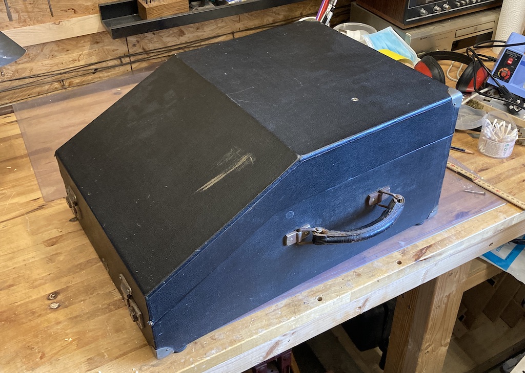
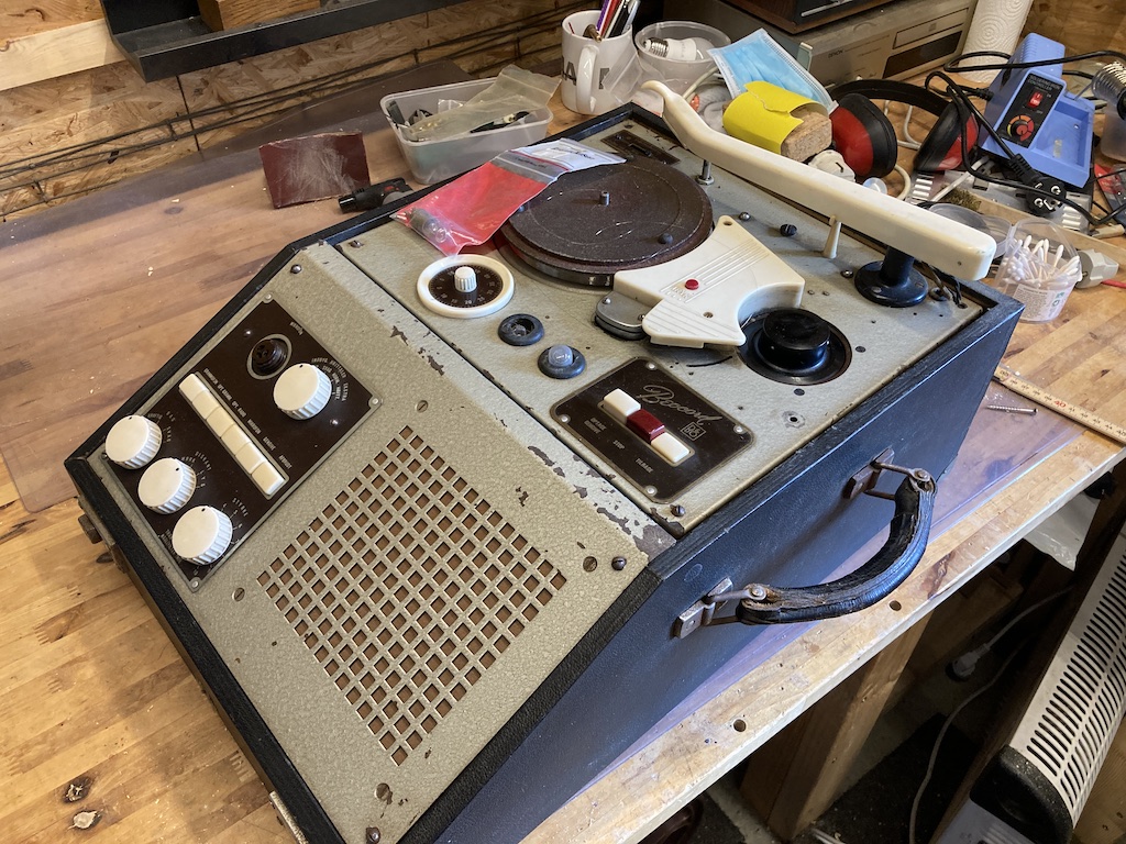
The Beocord 506UK incorporated a turntable with a fixed rotation speed of 78 RPM, with a mono output (of course…). The take-up spool of for the magnetic wire recorder doubled as the turntable platter, which makes it easy to ensure that it’s running at the correct speed (there’s an adjustment screw just on the other side of the white plastic plate on the top between the two wheels).
It was possible to record directly from the turntable output or from the microphone input (the connector is on the top left of the front panel). It had a built-in loudspeaker, so it was a stand-alone “portable” device.
My intention was only to get the magnetic player up and running – not to restore the entire device, so I donated all of the extra parts that I didn’t need to keep to a friend of mine who repairs and restores old B&O equipment.
Step 1 was to remove the player from the rest.
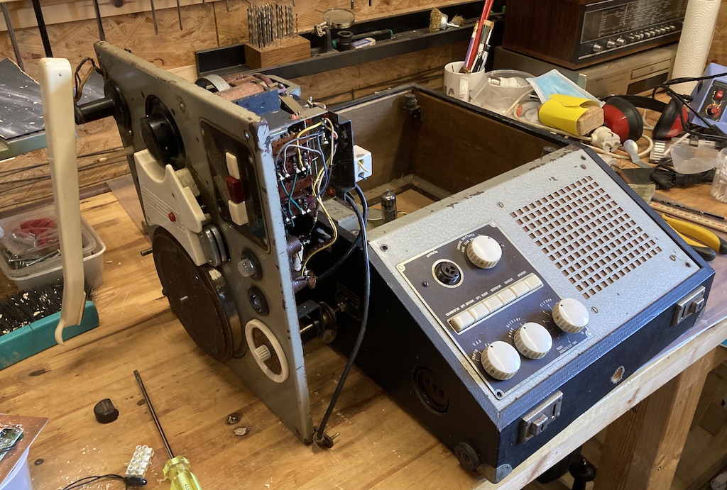
This means being a little careful, since that angled casing that you see on the right of the photo below is made of asbestos. Luckily, the nice people at the local dump know how to deal with this, so they were willing to take it off my hands.
Notice as well that, in the 1950s, B&O wound its own transformers.
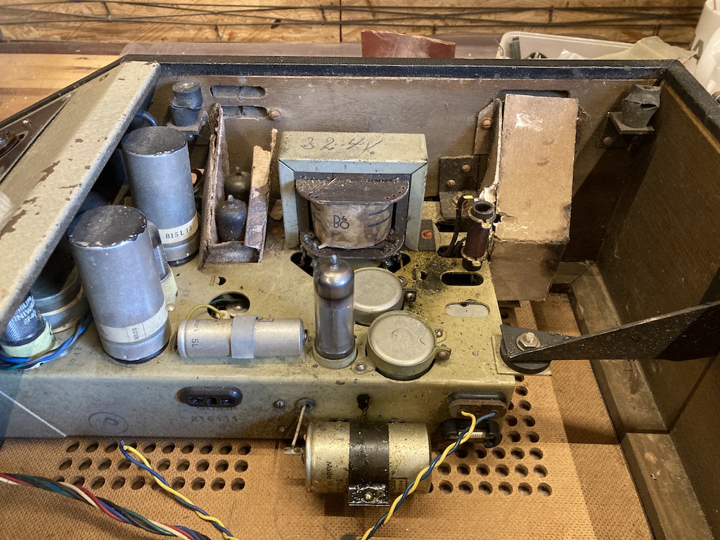
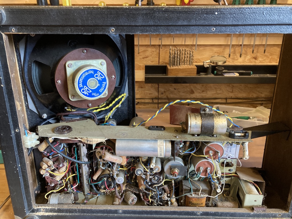
Back in those days, B&O also made its own custom loudspeaker drivers. This one is still in reasonably good condition, so I kept it with the plan to connect it to a modern amplifier for listening to the magnetic wire recordings.
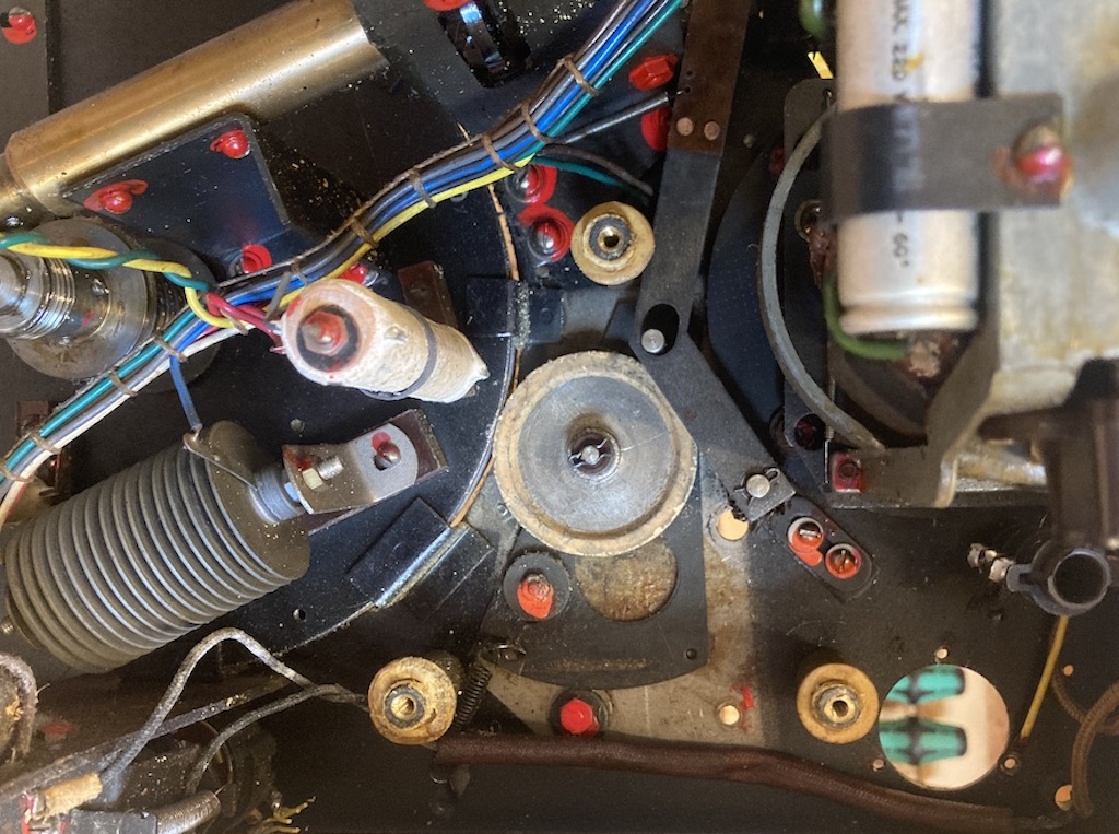
One problem with these old Beocord players is in the idler wheel that sits between the motor drive shaft and the outside edge of the take-up spool. This is the metal wheel with the white rubber edge in the middle of the photo below. The problem is that, over the past 70 years, this rubber has not only shrunk, but it has hardened, so there’s no friction to drive the spool.
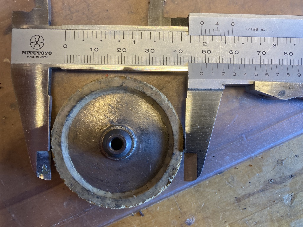
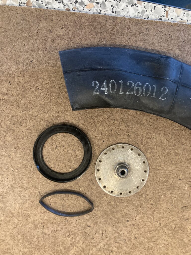
One solution to this is to put the wheel on a lathe, reduce the diameter of the (now hard) rubber, and glue on an elastic band. This works well. I took a different path. I first got a rough measurement of the outside diameter of the wheel as a starting point.
I then cut, filed, and sanded off all of the old rubber. I 3D printed a new edge ring which is glued to the metal wheel. I then cut a strip out of a bicycle inner tube and glued that to the edge. I used Loctite Extreme for both, since it works on metal, plastic, and rubber, and remains flexible after curing. The truth is that this took 4 different attempts to get things working correctly. The last version needed only a 0.5 mm reduction in the diameter to get it behaving.
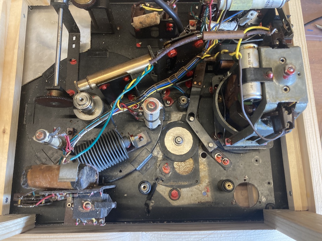
The “new” idler wheel can be seen in the photo below, back on its axle. It sits on a triangular plate that is able to move a millimeter or two.
When playing a wire, the spring on the bottom-middle of the photo pulls the idler wheel against the edge of the take-up spool (the large circle on the left) and the axle of the motor (which has been removed in this photo).
When rewinding, the L-shaped arm is pulled to the right by an electromagnet, which pulls the triangular plate slightly upwards and to the right (in this photo). This reduces the amount of friction on the take-up spool, but still provides enough tension pulling against the rewind motor to keep the magnetic wire from spooling out of control and turning into a bird’s nest.
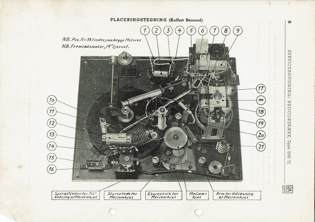
For reference, this is the photo from the original technical service manual. “Idler wheel” in Danish is “Mellem hjul”.
This is the final result. I’ve connected the output of the playback head to a standard RIAA preamplifier. It doesn’t have exactly the same response as the original, but it’s close enough. The output of the RIAA is connected to the analogue input of a Beoplay A1, which is what you’re listening to.
Notice that there is a mechanical link between the rotation of the take-up spool and the vertical position of the head. This ensures that the wire doesn’t bunch in the middle of either spool when you’re playing or rewinding. Also note that there is no “fast-forward” option. You only have PLAY, STOP, and REWIND. Due to the way I’ve wired up the head, it’s possible to listen to the output as you’re re-winding, however, this would be muted in the original Beocord.
Also note that I’m using an isolation transformer for the mains power – mostly to ensure that I don’t get electrocuted when I touch things, but also as a backup circuit breaker.
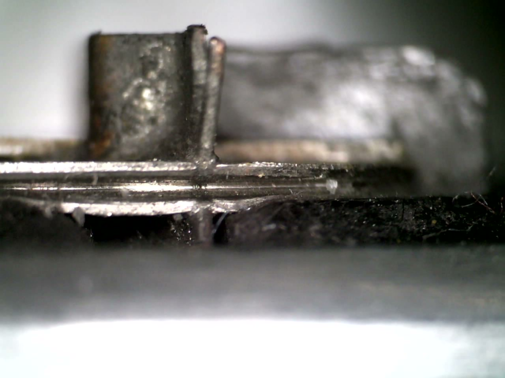
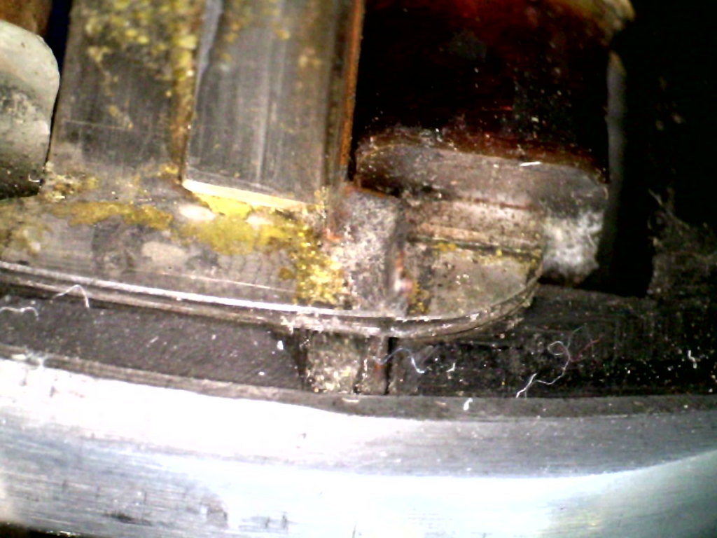
While I had things apart, I also used a USB microscope to take a look at the details in the playback head. Some of those photos are shown below.
The photo below shows the right side of the playback head looking down from the top. The wire runs in a groove along the front of the head which is the curve on the bottom of the photo. The coil of wire inside the orange lacquer generates a small electrical current when there is a change in the magnetic field in the gap directly below it.
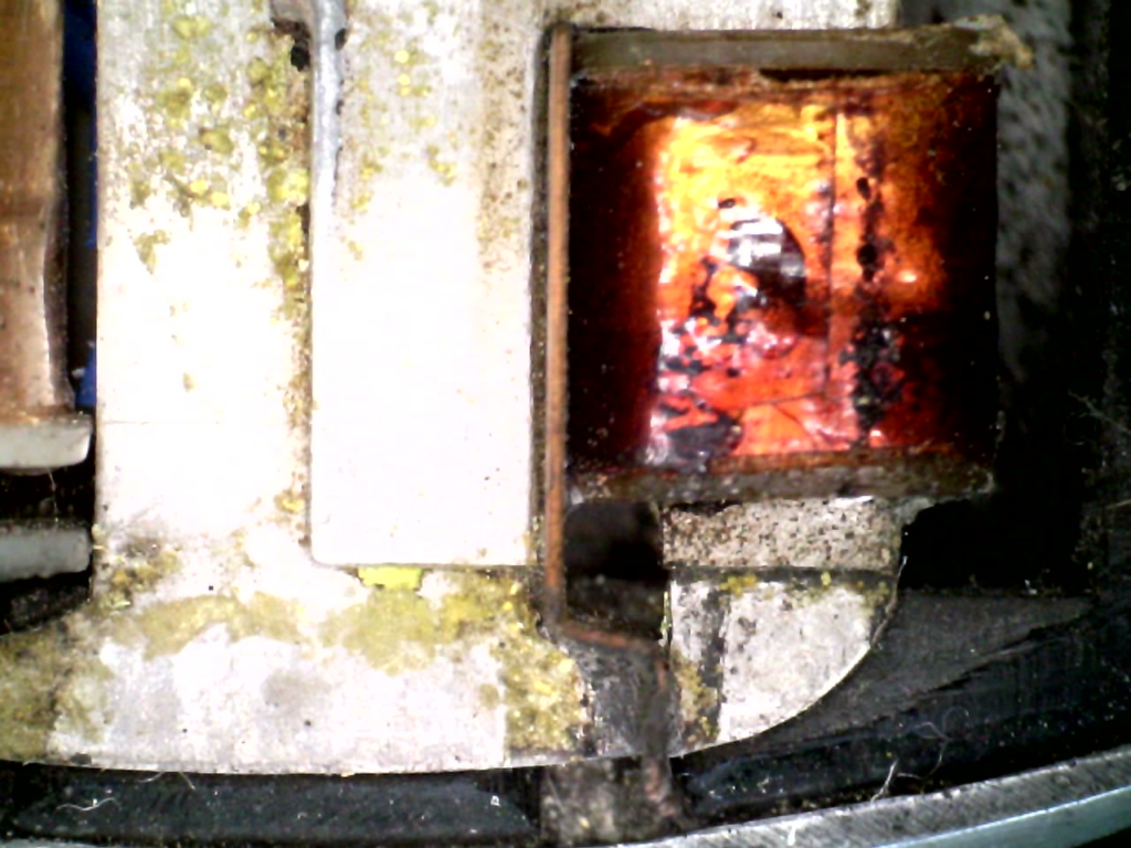
The photo below shows the same coil, looking from the front a little more. The gap is too small to be seen in this photo, but it’s at the location of the small discontinuity in the nice curve with the groove in it.
The photo below is looking directly into the front of the groove. The blurry silver shape in the upper right is the front of the coil shown above.