If you have a bunch of audio devices in a chain (say, a CD player connected to a preamplifier connected to a power amplifier connected to a loudspeaker) then one of the simplest things that you can do to improve or optimise your audio quality is to look after the gain of the signal through the system. It’s also free – and getting a lot for free is always a good thing…
Let’s start by taking a simple view of one device – a piece of audio gear. It doesn’t matter what the gear is – it could be an MP3 player, it could be a giant mixing console. What we’ll do is just look at the output of this device as it tries to play an audio signal with a varying level.
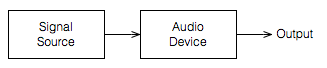
Let’s use a very simple example of a sine wave as our audio signal; we’ll look at the output of the Audio Device as we increase the level of our sine wave from very quiet to very loud.
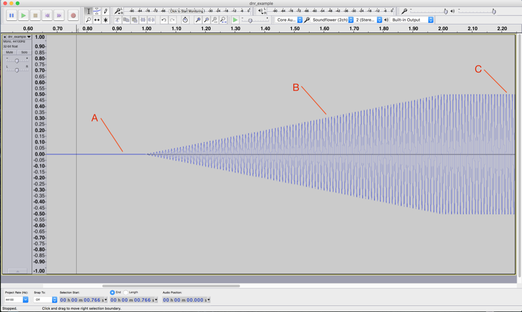
This screen shot shown in Figure 2, by itself, is not that interesting. Let’s zoom in to the three points on the plot to see what’s going on.
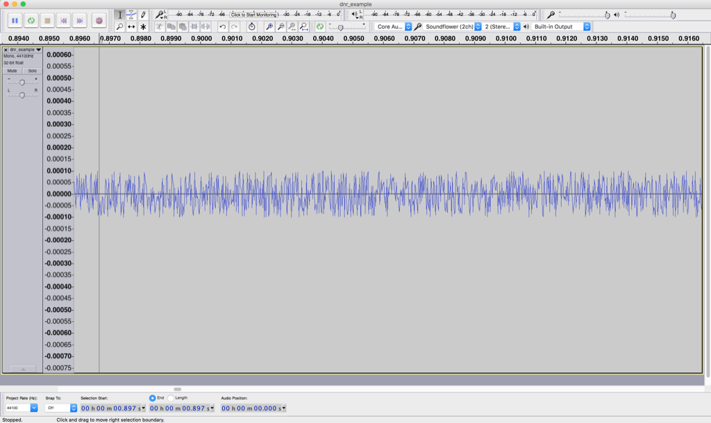
Figure 3 shows a zoomed-in view of point “A” in Figure 2. Notice that you cannot see a sine wave in that signal – it’s just noise. This is the noise that is naturally generated by the device for some reason. This may be natural noise in the analogue chain – caused by thermal movement of electrons in resistors, amplified by the device itself. It may be intentional noise like dither which is added to the signal to randomise errors in a digital audio chain. Or, it may be something else entirely…
But be careful not to jump to conclusions… Just because you can’t see a sine wave there doesn’t mean that you won’t be able to hear it. As the level of the sine wave is increased, we’ll be able to hear it along with the noise before we’ll be able to see it on the screen.
In this case, we have a very low “signal-to-noise ratio”. In other words, the level of the signal (the sine wave) divided by (because it’s a ratio) the level of the noise gives us a low number. Or, in normal English – the sine wave is “drowned out” by the noise.
Figure 4 shows a nice, clean-looking sine wave coming out of our audio device. It’s what’s going on at point “B” in Figure 2. We’ve zoomed in so much that you can’t see the increase in level over time – but trust me, it’s happening there.
The noise is still there, “riding the wave” of the sine tone. In fact, if we were to zoom in on the sine wave in that figure, we’d see the same kind of noise that we saw in Figure 3 – like little ripples on big ocean waves. Now, however, the sine wave is much louder than the noise – so we have a reasonably high “signal-to-noise ratio”. In other words, the level of the signal (the sine wave) divided by (because it’s a ratio) the level of the noise gives us a high number. Or, in normal English – the sine wave “drowns out” the noise.
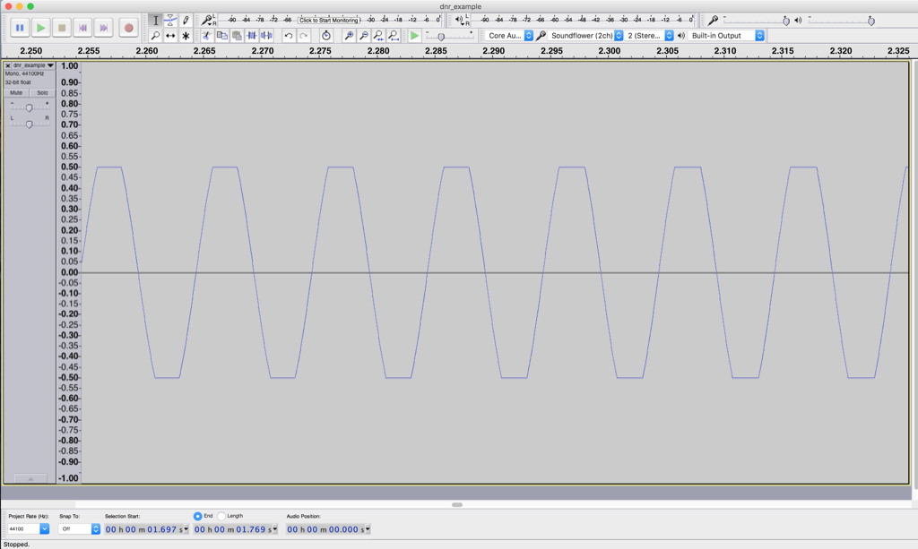
Figure 5 shows what’s happening at point “C” in Figure 2. Notice that this doesn’t really look like a sine wave any more – the top and bottom has been chopped off or “clipped”. This has happened because we are trying to make our audio device have an output level that is beyond its abilities. As the sine wave increases, the audio device follows along, until its output can go no higher, so it stops and holds that output level until the sine wave comes back down.
At the point, the noise is still very much lower in level than the signal – but we have caused a problem – the input is a sine wave, but the output is not. In other words, we have distorted the shape of the audio signal.
Note that distortion of an audio signal can take an infinite number of forms. The example here is symmetrical clipping of the signal – which is what many people mean when they say “distorted” – but don’t be fooled… “Distortion” means a whole lot more than this.
So, there’s a moral to the story-thus-far: every audio device has an upper and lower limit for audio level. (Yes, even a wire has a lower limit set by thermal noise in the electrons it contains and an upper limit set by the amount of current it will pass through before melting.) That range of dynamics or dynamic range is (hopefully) big – in other words, the noise floor (the quietest sound) should be MUCH MUCH quieter than a just-clipped signal (the loudest sound). Because this difference is so big, we’ll measure it in decibels (for kind of the same reason it doesn’t make sense to measure the speed of a car in millimetres per year, or the area of Canada in square micrometres.)
We can also represent these two numbers (the level of the noise floor and the level of a just-clipped signal) as two values relative to each other. Let’s say, for the purposes of keeping the numbers pretty, that we have an audio device that just so happens to have a level of noise floor that it 100 dB below the level of a signal that just starts to clip at its output.
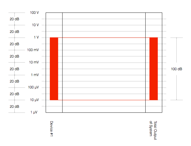
Figure 6 shows one way to represent this. The red vertical rectangle on the left shows the range of audio levels that is possible to achieve with “Device #1”. It has a noise floor of 10 µV and will clip at 1 V – therefore it has a total dynamic range of 100 dB. Since, in this example, Device #1 is the only device in our audio system, the dynamic range of the entire system is also 100 dB (shown as the ride rectangle on the right) – since the entire system consists of just one device.
What happens if we add another device in our chain? Let’s say, for example, that we put a second device in the system after Device #1. Let’s also say that Device #2 can play louder signals than Device #1 – and it has a lower noise floor, as is shown in Figure 7.
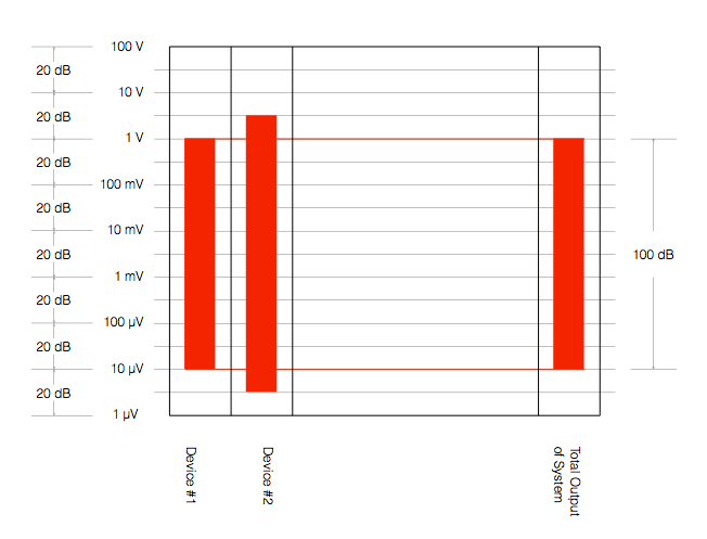
There are three things to notice in Figure 7:
- Device #2 can play louder than Device #1
- Device #2 has a lower noise floor than Device #1
- Therefore Device #2 has a wider dynamic range than Device #1
- The dynamic range of the total system is set by Device #1, since it is not limited by Device #2.
However, we should be careful here. The fact that Device #2 has a wider dynamic range than Device #1 does not automatically mean that the total system has a dynamic range that is defined by the “weakest link” (Device #1). Look at Figure 8, for example.
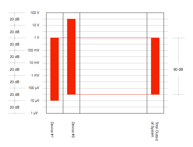
In Figure 8, we have not changed the devices – Device #2 still has a 120 dB dynamic range – but the Total System has a dynamic range that is reduced to 90 dB because of the alignment of levels in the system. Now, the noise floor of the system comes from Device #2 because we have not been careful about setting up the alignment of the levels of the devices.
Another way to think of this is that Device #2 is set up with the expectation that it will go much louder – but it doesn’t because of the limitations of Device #1. Because of that incorrect setup, the noise that you hear at the output of the system comes from Device #2.
An example of a system like the one shown in Figure 8 is when you connect a low-end audio device’s output (say, the headphone jack of your computer or phone) to a better device that is built to handle a much higher input level. The possible result is that the “headroom” (the amount by which the better device can handle higher level signals) is wasted (since the lower-quality device doesn’t deliver those high levels) and the total system has a degraded dynamic range.
So, the moral of the story here so far is that you should always try to ensure that your system’s dynamic range is not limited by the way it’s connected.
For example, if you have a system that has an adjustable input sensitivity, you should set it so that the input is not expecting more level than the device that’s feeding it can deliver. If your output device can only deliver 2 V RMS maximum, it my not be helpful for the thing it’s connected to to be “expecting” to see 4 V coming from it. If this is the way things are setup, then you might be “throwing away” 6 dB of dynamic range (because 4 V is 6 dB louder than 2 V).
Generally, there are two good “rules of thumb” that can help you here.
The first one is to try to align all your maximum levels as much as possible. So, as in the last example above, if your source device has a maximum output of 2.0 V RMS, set the input sensitivity of your next device to “expect” 2.0 V RMS maximum. This will make the tops of the red rectangles all align, and the dynamic range will be defined by the worst link in the chain instead of the way the devices are connected.
The second rule of thumb is to put as much gain as possible at the beginning of the chain. This is particularly true if you’re working in a recording studio. This is because every piece of gear contributes noise to the audio signal. If you put all the gain at the end of the chain, then you are making the signal louder, but you’re also making all of the noise from all of the gear “upstream” louder as well. If you put all the gain at the beginning of the chain, then you might wind up in a situation where you have to turn DOWN the signal through the chain, those reducing your signal to the correct level, and bringing the noise floor down with it. (Two obvious examples of this are using lots of gain at your mic preamp in a recording studio, or getting a RIAA preamp with a healthy output level for your turntable…) Another good example of this is the case where you have a headphone output from your phone connected to the aux input of a small stereo system. You want to turn up the phone as much as possible, and turn down the stereo volume. If you do the opposite, you’ll be using the stereo system to turn up the noise output of your phone.
One last thing: connecting devices digitally will probably help with your dynamic range, however, this is not necessarily always true. You certainly cannot make an automatic conclusion that a digital connection is better in all respects than an analogue one – or vice versa. For example, in some cases, the errors in a sampling rate converter at a digital input stage may result in a higher level of “noise” floor than the analogue noise caused by an analogue-to-digital converter on the same device. Or, it might be that these two inputs have the same measurable noise floor, but those two noises have very different characteristics. Typically analogue noise is program independent – meaning it’s unrelated to the signal – whereas poorly-implemented digital transmission and processing typically results in program-dependent errors. These can be interpreted by the listener as being part of the signal (more like distortion artefacts than noise) and therefore will be different for different signals. To make things even more confusing, different digital inputs on the same device (e.g. Optical, S/P-DIF, and HDMI) may (or may not) behave differently – so any decisions you make about one of them may (or may not) be applicable to the others…
Bart says:
Hi Geoff,
Is the thing you talk about here the same or comparable with using a gain knob on a car audio amp to match the output of the head unit to the input of the amp?
https://www.extremeaudio.org/what-is-a-gain-control/
It’s always fun to read your tech articles as they are very informative and very well written.
Every time I read a new one I keep discovering new things about audio and audio related thing I didn’t knew before.
It’s like they always say, people are never to old to learn.
Kind regards
Bart
geoff says:
Hi Bart,
The short answer is “yes”. :-)
…and thanks!
Cheers
-geoff