#16 in a series of articles about the technology behind Bang & Olufsen loudspeakers
Take a balloon and blow it up. It will look something like the drawing in the centre of Figure 1.

If you put your hands on the top and bottom of the ballon and compress them, you’ll make the balloon shorter, but you’ll also make it wider (as is shown on the left side of Figure 1). This is because the air inside the balloon is under a higher pressure when you squeeze your hands together, and that pressure pushes harder on the parts of the balloon that aren’t being held in by your hands.
If, instead, you grab the top and bottom of the balloon and stretch them further apart, you’ll make the balloon narrower (as is shown on the right side of Figure 1). This is because you’ve created more space inside the balloon, thus lowering the internal pressure pushing out on its walls. The lower the pressure, the less the air pushes outwards, so the balloon collapses.
What we’ve described here is basically the same as what happens to a sealed loudspeaker cabinet (if you’re not careful when you do its mechanical design). However, instead of your hands squeezing a balloon (a sealed “cabinet” of air), we use the signal from a power amplifier to pull the woofer into the cabinet. This increases the pressure inside the cabinet, since it’s sealed and there’s nowhere for the air to go. As a result, the trapped air tries to push outwards on the sides of the cabinet. If the walls of the cabinet are thin, then the cabinet itself will act like the balloon and expand.
Similarly, if you put a positive signal on the power amplifier, you’ll move the woofer out of the cabinet, reducing the air pressure inside it and “sucking” the sidewalls of the loudspeaker in (if they are so thin that they can move).
Generally speaking, you want a loudspeaker to behave as a piston in a baffle (like this). This means (in this case) that you want the woofer to move in and out of a loudspeaker cabinet and you don’t want the cabinet itself to move at all. (We’ll talk later about why this is a bad thing.)
There are a number of different ways to do this. One way is to make your loudspeaker cabinet out of something very, very, very stiff (and probably, as a result, very, very, very heavy). For example, we make our prototypes out of 22 mm or 25 mm thick MDF (and sometimes we use two sheets of it, glued back to back, to make sure that things are stiff enough). Most of our loudspeakers like the BeoLab 9, for this week’s example, have enclosures that are made of plastic, so we use some different methods to achieve the stiffness and rigidity we need to ensure that our enclosures are not singing along with the drivers.

The first step in ensuring that the walls of the loudspeaker cabinet are stiff enough is to make them thick enough. How thick is “enough” depends on the loudspeaker itself. A subwoofer with a small enclosure volume will have to withstand more internal air pressure than a midrange in a larger enclosure. Of course, we can’t simply make the walls of the cabinet out of overly thick plastic, since that would not only be an unnecessary waste of materials, it would increase the weight of the loudspeaker (a consideration for shipping) and the cooling time of the plastic when it’s in production (a consideration for the production line timing and costs).
A second way to make the sidewalls stiffer is to use ribs – usually on the inside of the cabinet. These are moulded as part of the sidewall itself – they aren’t just glued on to the inside surface of the cabinet. If you take a look at Figure 3, you can see the ribs on the inside of the sidewalls of the BeoLab 9. These run diagonally and vertically in the case of this loudspeaker – but they’re not just randomly placed inside the loudspeaker. They have been strategically placed using simulations in the early development stages, and measurements of the early prototypes. These measurements are done using very small accelerometers glued to the sides of the loudspeakers and monitoring their outputs while playing signals through the loudspeaker drivers. (In case you’re wondering, the depth of the ribs is about 22 – 25 mm, depending on where you measure.)

A third tactic is to use a plastic that is stiffened by adding things to it. The usual method is to use fibre-reinforced plastic. The fibres in the plastic help give it a structural strength that you can’t get from just plastic alone.
A fourth possibility is to create a laminate material where you build up the enclosure using layers of different materials (or layers of the same material with different structural composition). This increases stiffness in the same way that a sheet of plywood is stiffer than a sheet of wood.
So, in the case of the BeoLab 9 (as with many of our other loudspeakers), three of these tactics were used. The plastic is thick enough, it has strengthening ribs on the inside, and it is a laminate (if you slice it open, you’ll see that it is a layer of foamed plastic, sandwiched between “skin” layers of solid plastic).
However, when they (I wasn’t part of the BeoLab 9 development team – I was still working in the Automotive Department at the time) got to the last stages of the development, it became obvious that there was a problem. There was an audible resonance caused by the woofer. Some digging around resulted in the finding out that the sides of the cabinet were moving too much. In essence, the problem was almost exactly as I described with the balloon in Figure 1.

As I tried to show in Figure 4, when the woofer moved inwards, it pushed the sidewalls of the loudspeaker outwards (shown with the blue lines). When the woofer moved outwards, it sucked the sidewalls inwards (the red lines). (I’m over-simplifying here, but not enough to start a fight.)
However, as I said, this was discovered rather late in the development process. The problem had to be fixed, but the question was how to do it without starting from scratch and creating new moulding tools for making the plastic enclosure. The solution was to use the sidewalls to reinforce each other. Since the movement of the opposite sides was in opposite directions (i.e. the left and right sides of the loudspeaker either wanted to move apart or together at any given moment) they could be braced by connecting them with a bridge. Take a look again at Figure 3. You’ll see a metal rod that goes straight across the middle of the woofer enclosure. You can see it just above the back of the woofer in Figure 5 as well.
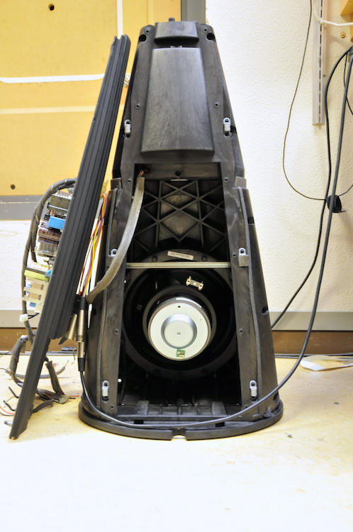
That piece became known in the acoustics department as the “dog bone” because its final version had the basic shape of a cartoon dog bone. The end result is that the rod is included in the BeoLab 9 construction to prevent the sidewalls of the woofer cabinet from moving when you’re playing loudly.
Here’s another photo showing the internal PCB with the amplifier and filters – not because it’s relevant to this discussion, but just because it might be interesting…

How is a loudspeaker cabinet like a nude ballet? (Or: so what?)
So, we’ve seen how we get rid of parts of the loudspeaker moving when they shouldn’t. The question is “why is it a big deal?” Well, it’s a little like Sir Robert Helpmann’s comment about the difficulties in choreographing a nude ballet – the problem is that some parts of the body keep moving when the other parts have stopped.
In theory, a loudspeaker should behave the same at all frequencies (that statement can mean a lot of different things – and I am happy to argue that it is both true and false, depending. So don’t try to start a fight with me on that one, and please don’t mis-quote me and say that I’m contradicting Siegfried Linkwitz or anyone else by taking that statement out of context on a hi-fi forum somewhere else…) As I mentioned in a previous posting, we like to pretend that a loudspeaker is just a moving piston in an infinite baffle, since that behaves pretty well. Of course, no one actually believes that this model is true – but it’s a comforting ideal.
Take a look at the shape of the blue and red versions of the loudspeaker cross-section in Figure 4, above. You might notice that, when the woofer goes outwards, the cabinet goes inwards. When the woofer goes inwards, the cabinet goes outwards. (this is an oversimplification of the truth, but let’s go with it for now). This means that, from the point of view of the air pressure radiating from the entire loudspeaker, the woofer goes positive and the cabinet goes negative at the same time. So, the sound pressure radiating off the cabinet cancels the sound pressure radiating off the woofer as can be seen in an example of two opposite-polarity sources causing destructive interference as in the animation below. (Note the intersection of the red and green curves where you will hear no sound at all…)
Not only that, but the cabinet as a sound source has a very different directivity than the woofer by itself. So, the result is… complicated. The truth is even more complicated, since the cabinet will not behave as nicely as this – it will resonate better at some frequencies than others, making some notes “bloom” – they’ll appear to be louder (or quieter, depending on where you are and how the room interacts with the loudspeaker) and they might even appear to come from a different direction.
So, the moral of the story here is that you want all parts of the loudspeaker to not be moving when the parts that are supposed to be moving are doing so.
And, before you go and listen to your loudspeakers and look for “blooming” and blaming it on panel resonances or vibrating cabinets, don’t forget that your room modes are more likely a primary source of mis-behaviour when it comes to some bass notes sounding different from the others. However, if you have problems with your room acoustics, we can’t fix that with ribs and dogbones – unless you also bring in a large dog. (I know, I know – the linked paper is about humans – but it does make a mention of animals in the abstract…)