#41 in a series of articles about the technology behind Bang & Olufsen loudspeakers
Most loudspeaker projects at Bang & Olufsen are conceived in the design or the Product Definition department. This means that someone decides something like “we’re going to make a loudspeaker, this size with this design” and then the project arrives at the Acoustics Department to find out whether or not the idea is feasible. If it is, then it continues through the development process until we reach the end where the is a product in a store. A better description of this process is in this posting.
BeoLab 90 was different. Instead of being a single project that began, evolved, and ended, it was more like a number of little streams coming together to form a river. Each stream was an idea that contributed to the final product.
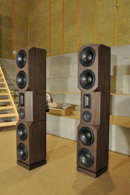
One of the early “streams” was an idea that was hatched in the Acoustics Department itself around 2009. I went to the head of the department at the time, and offered to make a deal. If I were to pay for all the components personally, could I use my work hours and B&O resources (like the Cube) to build a pair of loudspeakers for home. These would be a “one chair – no friends” style of loudspeaker – so it would not really be a good candidate for a B&O loudspeaker (our customers typically have friends…). In return, I would keep the loudspeakers in the listening room at B&O for an extended time so that we could use them to demo what we are capable of creating, without our typical restraints imposed by design, development time, size, “normal” product requirements (like built-in amplifiers and DSP), and cost of components.
By early 2011, these loudspeakers were built (although not finished…) and ready for measurements and tuning. The photo below shows the “raw” loudspeaker on the crane in the Cube going out to be measured.
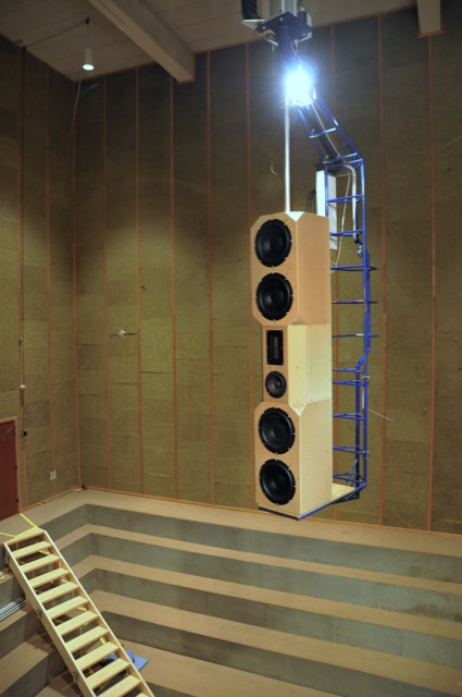
Those loudspeakers lived in Listening Room 1 for about a year. We’re bring people in for a “special demonstration” of a loudspeaker behind the curtain. The general consensus was that the loudspeakers sounded great – but when the curtain was opened, many people started laughing due to the sheer size (and the ugliness of my design, apparently…) of the loudspeakers.
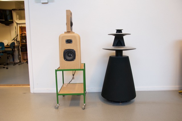
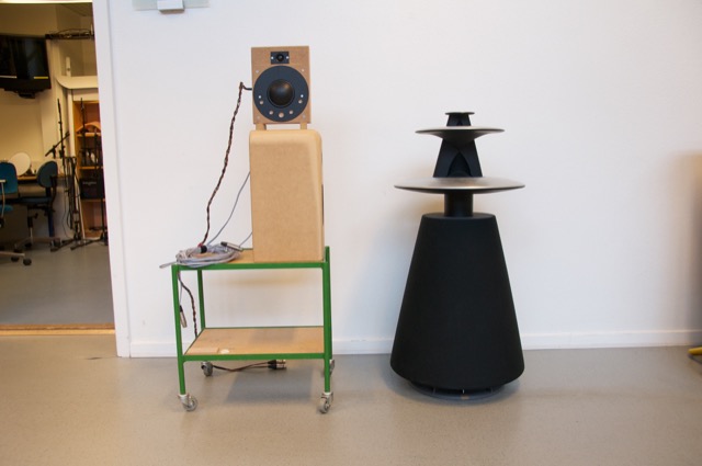
The second “stream” was an idea that was born from Gert Munch’s goal of building a loudspeaker with a smooth power response as well as a flat on-axis magnitude response. The experiment was based on a “normal” two-way loudspeaker that had an additional side-firing dipole on it. The basic idea was that the two-way loudspeaker could be equalised to deliver a flat on-axis response, and the dipole could be used to correct the power response without affecting the on-axis sound (since the on-axis direction is in the “null” of the dipole). For more details about this project, please read this post.
After the “shark fin” experiment, we knew that we wanted to head towards building a loudspeaker with some kind of active directivity control to allow us to determine the amount of energy we sent to the nearby walls. Two members of the Acoustics Department, Gert Munch and Jakob Dyreby, had been collaborating with two graduate students (both of whom started working at B&O after they graduated), Martin Møller and Martin Olsen on exactly this idea. They (with Finn Agerkvist, a professor at DTU) published a scientific paper in 2010 called “Circular Loudspeaker Arrays with Controllable Directivity”. In this paper they showed how a barrel of 24 small loudspeaker drivers (each with its own amplifier and individualised DSP) could be used to steer a beam of sound in any direction in the horizontal plane, with a controlled beam width. (That paper can be purchased from the Audio Engineering Society from here.)
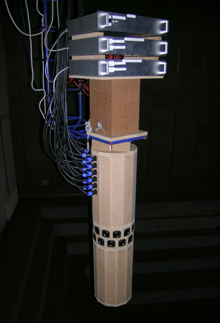
The next step was to start combining these ideas (along with other, more developed technologies such as Thermal Compression Compensation and ABL) into a single loudspeaker. The first version of this was an attempt to reduce the barrel loudspeaker shown in Figure 6 to a reasonable number of loudspeaker drivers. The result is shown below in Figure 7.
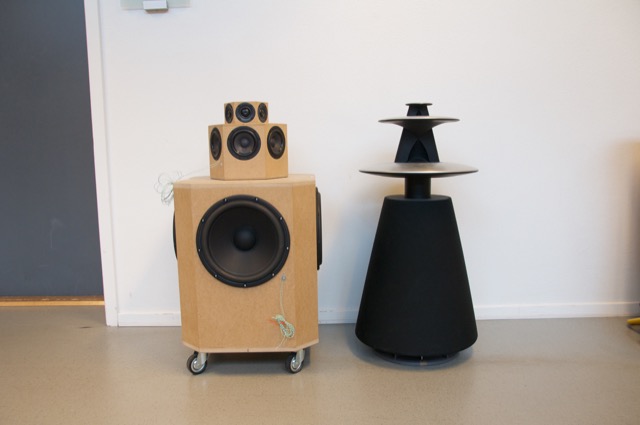
This first prototype had a hexagonal arrangement of tweeters and midranges (6 of each) and a square arrangement of woofers. Each driver had its own DSP and amplification with customised filters to do the “usual” clean-up of magnitude response in addition to the beam steering much like what is described in the AES paper.
Unfortunately, this version was not a success. The basic problem when trying to do directivity control actively is that you need the loudspeaker drivers to be as close together as possible to have control of the beam width in their high-frequency band – but as far apart as possible to be able to control their low-frequency band. In the case of prototype 1, the drivers were simply too far apart to result in an acceptably constant directivity. (In other words, the beam width was different at different frequencies.) So, we had to try to get the drivers closer together.
For the second prototype (shown below in Figure 8, 9, and 10) we decided to try to forget about a steerable beam – and just focus (forgive the pun) on a narrow beam with constant directivity (the same beam width at all frequencies). In addition to this, we experimented with a prototype 8mm supertweeter that would take care of the band from about 15 kHz and up.
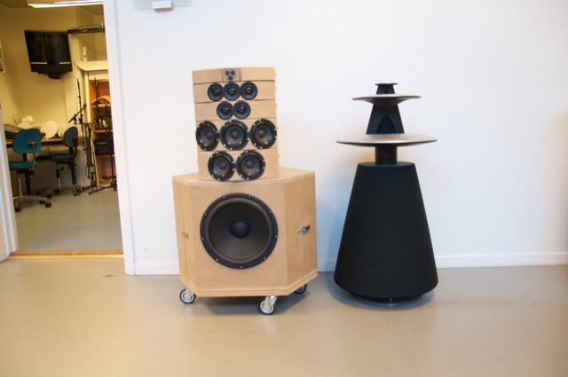
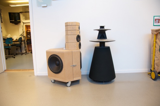
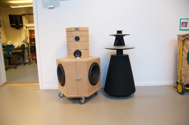
Although Prototype #2 sounded great in the sweet spot, it lacked the versatility of the first prototype. In other words, it was an amazing loudspeaker for a person with one chair and no friends – but it was not really a good loudspeaker for sharing… So, we started working on a third prototype that merged the two concepts – now called “Beam Width Control” and “Beam Direction Control”. The result in shown below in Figures 11, 12, and 13.
As you can see there, the “cluster” of 3 tweeters and 3 midranges comes from prototype 2 – but we re-gained side-firing drivers and rear-firing drivers to be able to steer the sound beam in either of 4 directions. The Beam Width could only be controlled for the front-firing beam, since it is a product of the cluster. You’ll also notice that the super tweeter was still there in this prototype. However, we also changed to a different tweeter and were starting to question whether the extra 8mm driver (and its amplifier, DAC and DSP path) would be necessary.
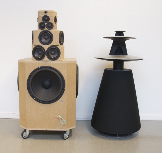
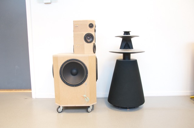
One thing that any good acoustical engineer knows is that corners cause diffraction. This is well-known at B&O as you can read here. Looking at the enclosure for the midranges and tweeters in the three previous figures, you can see many flat surfaces and corners – which, we assumed, were bad. So, we set about on an informal experiment to find out what would happen if we smoothed out the corners in an effort to reduce diffraction – or at least to change it. This was initially done by applying putty to the MDF enclosures and measuring the off-axis response of the result. One example of this (in progress of bring coated with putty – this was not the final version – it’s just there to show the process) is shown below in Figure 14.
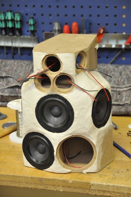
Surprisingly, we found out in these tests that the “smoothing” of the structure around the midranges and tweeters either made no difference or made things worse. So, we continued on, knowing that the final result would be “smoother” anyway…
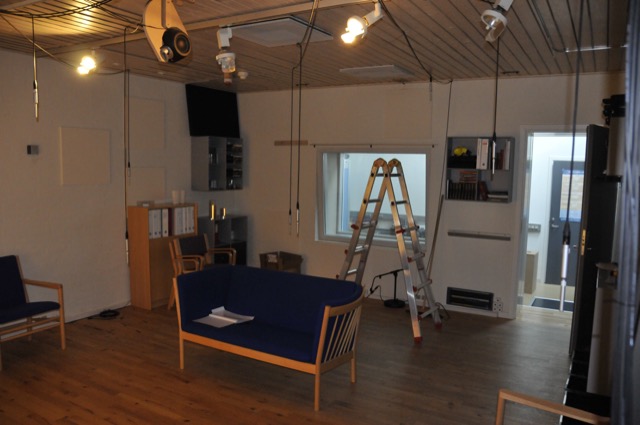
While that work was going on in the Cube, a third “stream” for the project was underway – the development of the Active Room Compensation algorithm. In the early versions, it was called “ASFC” or “Active Sound Field Control” – but as time went on and the algorithm evolved, we changed to a different system and gave it a different name. Photo 15, below, shows the listening room during one of the tests for the original algorithm. I count 9 microphones in there – but there may be more hiding somewhere.
All of the prototypes shown above are just loudspeaker drivers in MDF enclosures. All of the DSP and amplification (in a worst-case, 17 channels in total per loudspeaker) were outside the loudspeakers. In addition, the amplifiers needed active cooling (a fancy way to say “fans”) so they had to be in a different room due to noise. The photo below shows the rack of DSP boxes (on top) and amplifiers (4 channels per box) used for the prototyping.
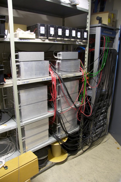
While this equipment was being used to evaluate and tune the complete prototypes, a parallel project was underway to find out whether we could customise the amplifiers to optimise their behaviour for the use. For example, if you know that an amplifier will only be used for a midrange driver, then it doesn’t need to behave the same as if it were being used for a full-range loudspeaker. I’ll describe that development procedure in a future blog posting, since it’s interesting enough to deserve its own story.
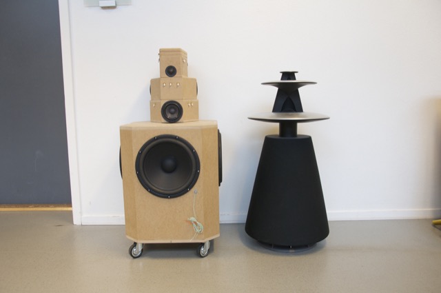
Finally, we were at a point where we built a first prototype of the “real thing”. This was hand-built using 3D-printed parts and a lot of time and effort by a lot of people. The first example of this stage is shown below on the crane in the Cube, sitting next to Prototype #4 for comparison. Notice that, by now, we had decided that the supertweeter was unnecessary, since the Scan-Speak tweeter we’re using was reliable up to at least 40 kHz. The only significant difference between the 4th prototype and the mechanical sample is that the wooden version has only one tweeter and one midrange pointing directly backwards. The “real thing” has two, aimed slightly towards the Left Back and Right Back. (See the Technical Sound Guide for more detailed information about this.)
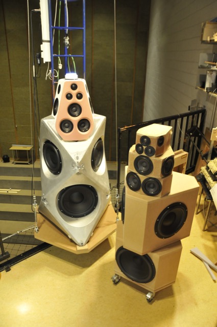
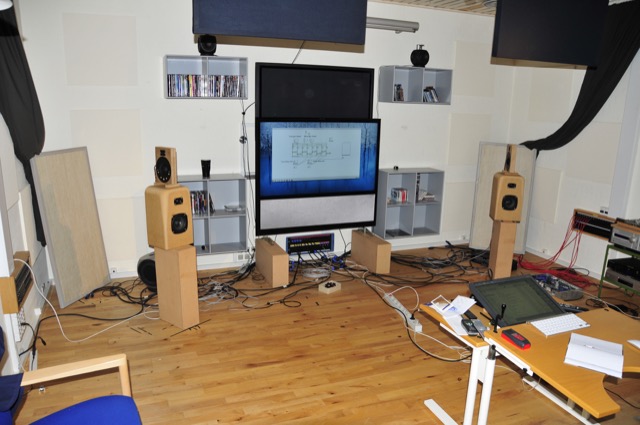
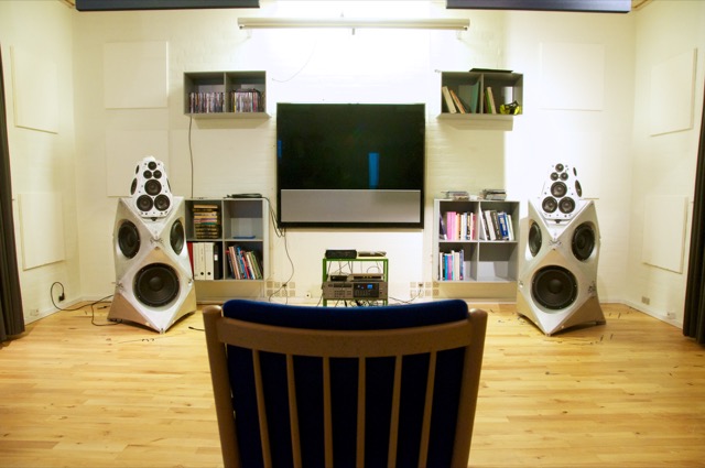
Once the measurement of the first mechanical samples were done and the correct filters programmed into it, it was time to move a pair into the listening room to see (or, more importantly, to hear) if they performed the same as the wooden prototypes. The first setup of device numbers 2 and 3 (the first one stayed with the electronics team for testing) in Listening Room 1 in Struer is shown below in Figure 18. For reference, the room is 6 m deep x 5 m wide – and that’s a 55″ BeoVision 11 on the wall.
When we did the measurements on the samples shown in Figure 18 – both in the Cube and in the listening room, we could see that there was an unusual (and unexpected) dip in the on-axis magnitude response of about 1 dB at around 8o0 Hz. Unfortunately, it did’t seem to be easily correctable using filtering in the DSP, which meant that it was probably the result of a reflection somewhere off the loudspeaker, cancelling the direct sound at the listening position. After a day or two of playing with putty placed in various locations around the loudspeaker, we found that the problem was caused by a reflection off the “shelf” just below the face of the top unit. That can be seen in Figure 19, below.
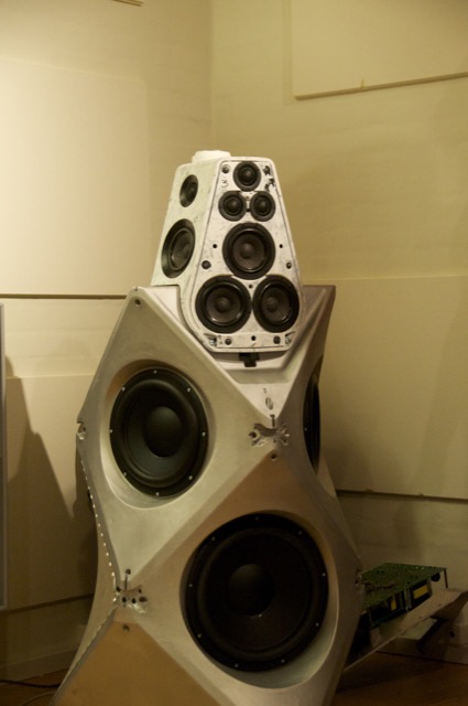
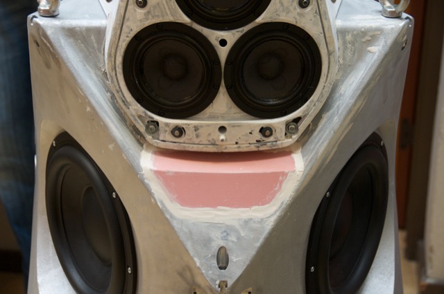
The way to correct this problem was to bring the height of the shelf up, which also meant that it was closer to the face of the top cluster. (Note that the front panel is missing in Figures 19 and 20 – the actual face is the pink panel seen in Figure 22.) This fixed the problem, but it meant changing the mould for the aluminium enclosure. In the meantime, while that change was happening, we were able to 3D-print an insert of the same shape that could be used for the listening reference pair of loudspeakers. This meant that we didn’t have to wait for the new aluminium versions to start tuning.
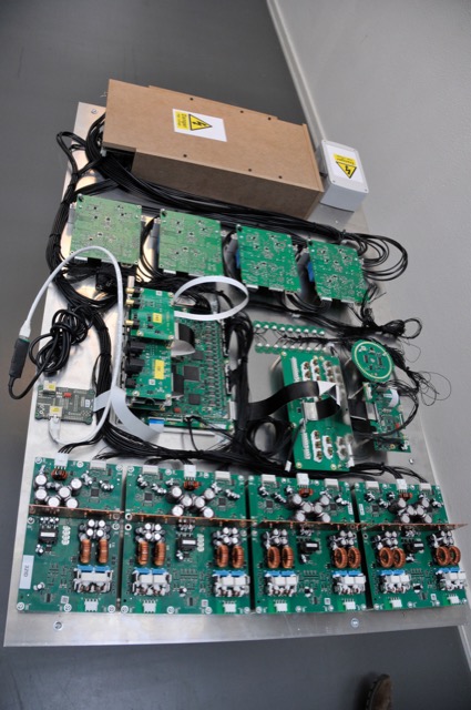
Of course, the electronics team developed their components on a test bench, piece by piece. Eventually, all of those pieces came together into a single unit (minus the loudspeaker drivers and enclosures) which could be used for testing and software development. An example of one of those test boards (actually, the first one of its kind to be made – and one of the few with all of the amplifiers attached…) is shown below in Figure 21.
I’ll probably show some better photos of the DSP board in a later posting.
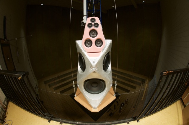
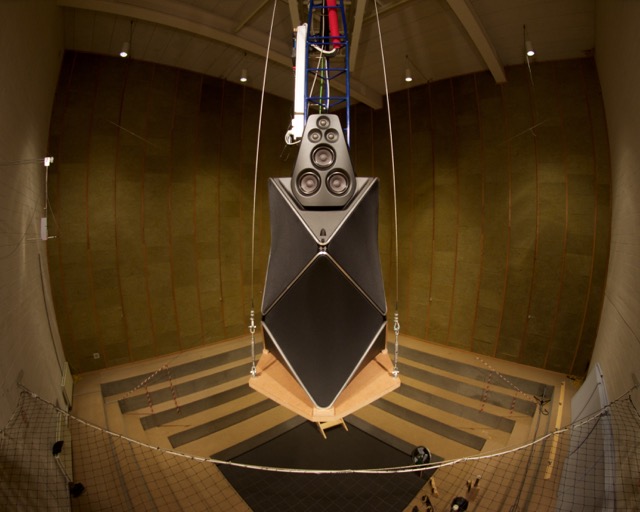
Finally, everything came together into a product that, acoustically and electrically, was identical to the production model. This is the version that we use for sound design. It’s shown (about to go out into the Cube for yet another round of measurements) in Figures 22 and 23, below.
Gary Eickmeier says:
Hi Geoff –
South Miami is a long way from here. I will keep that location in mind, but wouldn’t there be somewhere in Orlando or Tampa?
Thanks,
Gary Eickmeier
geoff says:
Hi Gary,
The only store location I was given was the South Miami location. Sorry.
Cheers
– geoff
Brian says:
Hi Geoff,
Fascinating articles on audio and the Beolab 90. In fact I was inspired to go audition the Beolab 90 because I believe this is a real step forward in advancing speaker performance.
Unfortunately, I had a rather poor audition because the B&O store I went to in Toronto did not set them up correctly. To start off, both speakers were playing the left channel. I was not impressed from the first listen, as the sound was dry and the imaging had no depth or width to it. Then by the second song I knew 100% why because there were some sounds that was almost completely missing, and it was only in the right channel (Bon Jovi’s Wanted Dead Or Alive, the 4 notes in the right channel that happens in the first 10 seconds of the song).
Even when that was corrected, the speaker still didn’t blow me away. The biggest problem was the imaging. The center image leaned to the right, and everything was very fuzzy. I could hardly locate the sound, let alone pinpoint the location. I did not really hear a difference between wide and narrow mode, which strongly suggests to me the speaker was improperly set up.
The other problem was I didn’t feel the speaker didn’t sound anywhere near as detailed or, just flat out good sounding as I expected. I actually built a speaker myself with the same Illuminator D3004/602010 tweeter and a similar, but lower quality midrange (the Discovery 10F/8424G). I didn’t feel it really sounded better than my own speaker, which is nonsense. I have no fancy DSP algorithms, no room treatment, no directional steering, or fancy engineering in my speaker. I expected the Beolab 90 to completely blow my speaker away, but it didn’t. That has to be because the setup is faulty.
On the good note, the bass absolutely blew me away. The best I’ve ever heard, bar none, from any speaker or subwoofer, and I’ve heard some extremely good subwoofers before being a bass head first and audiophile second. This is what I expected from the Beolab 90, to blow me away thinking this is the best I’ve ever heard, but in every audio performance category. Not a speaker that sounds like a good $5000 speaker instead (ignoring the 11/10 bass performance).
That’s why I felt I needed to inform you of this. You’ve put a lot of work in this speaker, and I hate to see something amazing being crippled by poor setup. I’ve told the salesperson of my opinion. While he is a very nice man, and a class act throughout the audition, I don’t think he’s going to do anything about it. I’m hoping you can do something about it, because it’s an insult for a speaker like the Beolab 90 to sound like what I heard that day, and completely unacceptable for a store to set up a $80,000 flagship speaker so poorly that both speakers were playing the left channel.
geoff says:
Hi Brian,
Thanks for the heads-up – and the (very likely) correct diagnosis that something more than two left
shoesspeakers is wrong with the system that you heard. The description you give doesn’t sound like the Beolab 90 that I know…I’ll forward your comments on to some people internally and ask that they look into it.
Thanks again!
Cheers
-geoff
Jon says:
Hey Geoff,
I’m more interested in the specifics of your “ugly speakers”. Xover points, slopes? How did you incorporate baffle diffraction compensation? 3 way, 3.5 way design? Active, or passive? Any DSP correction applied? Does the vertical directionality of the ribbon mess with the power response around the Xover point between it and the midwoofer?
Sitting here trying to make guesses in my head about your speaker design…
Thanks for your time!
geoff says:
Hi Jon,
some quick answers without explanations:
– The entire loudspeaker is active. DSP correction applied on individual drivers, and on the total response, both for “sound design” and a customised room compensation.
– it’s a 3.5-way design. The crossover between the mid woofer and the 10″ just below it is at 80 Hz. It’s a 4-th order Linkwitz-Riley (including compensation for the compensation of the drivers). The other three 10″ woofers roll in from 40 Hz and down. One reason I chose the mid woofer was that I wanted it to go down to 80 Hz, and that driver has a great Bl curve that let me do this and still keep control of the driver.
– The crossover between the mid woofer and the ribbon was set to around 2.5 kHz (I don\t remember the precise number). This was chosen because it was the frequency where the two drivers had matched directivity in the horizontal plane. Again, the crossover was a 4th order L-R, again with compensation. (which was necessary due to the rather weird roll-off of the tweeter in its low-end)
– One of the design goals was to keep crossovers out of the vocal range – hence the 80 Hz – 2.5 kHz bandwidth of the mid woofer. Matching the directivities of that and the tweeter also helped. This keeps the perceived distance coherent in the phantom images when you have strong sidewall reflections in the listening room.
– Before the sound design and room compensation process started, the on-axis response was pushed to go from 10 Hz ((-6 dB) because, in my opinion, 20 Hz is not low enough. You can’t hear this as “low end” – more like a “pressure” in the room up to 40 kHz (not because I can hear 40 kHz, but because it was possible…)
– The directivity of the tweeter is fine in the horizontal plane, but a complete mess in the vertical plane, so the 3D Power Response of the loudspeaker isn’t pretty… I measured a 10 dB roll-off at 10 kHz at 10° off-axis going vertically. This was easily audible – if you wanted less high-end, you just had to stand up…
– Every driver is in its own individual sealed cabinet (there are internal bulkheads). in addition, each tower is just 3 separate cabinets that are laid on each other. So, in the future, I can just put the mid-second on a speaker stand and use it as a two-way.
The baffle diffraction is another story… The bevelled corners on the mid-section helped a lot (this was the 3rd “prototype” for the front baffle) – but the goal there was just to get the edges in as close to the drivers as possible. Rounding those bevels would have smeared the diffraction in space and therefore time – so it moves the problem, but does not solve it… really…
If you have more questions, please feel free to ask!
Cheers
– geoff
Jon says:
Hey Geoff,
That’s a dangerous invitation! I could probably bug you with questions for weeks… My dream when I was a teenager was to design speakers for a living.
Anyway, I ended up an electrician, but I’ve been building my own amps and speakers for a long time now. Your use of that Fountek ribbon was actually what prompted me to ask you about your design in the first place. I’ve been kicking around in my head a rather large format 3.5 way “wwmtmww” speaker design, but I’ve never used a ribbon before, and wanted to do something a little different this go around.
Okay, so here goes one more round of questions, since you invited me, and then I’ll leave you alone. :)
The ribbon – you were building a speaker whose sound you wanted to be impressive to people who couldn’t (initially) see what was behind the curtain… What qualities of the Neopro5i prompted you to use it, versus say, the Scan dome tweeter in the BL90? I’m assuming the Scan probably measures lower in all types of distortion (IM, HD [although I must say, from the measurements I’ve seen floating around on the internet, the 2nd HD is creeping up on some of the Scan Speak tweeters in the low end of their range, even though the odd order harmonics are commendably low]), and would obviously have far better vertical dispersion (a debatable benefit). I also know a distortion plot isn’t the last word in whether something sounds good or not.
Speaking of distortion and linearity, how do you guys conduct your driver testing? Do you do your own klippel analysis in-house?
The subwoofers that you used in your “ugly speakers” (a 90’s Beolab 8000 they may not be, but I wouldn’t agree that they’re ugly, they’re cool in their own right) – how are the motors designed? Over/underhung, undercut poles, full copper sleeve, aluminum rings, double/single spider, round/flat wire VC, two/four layer, kapton/aluminum former, etc.? They look close to either a Peerless SLS or X/XLS (I’m guessing they’re a custom version for you guys?), but I could be totally wrong of course.
SEAS’s 10” Lroy subwoofer looks awesome. Haven’t tried it though. Of course, so does the Scan 13” you guys used in the BL90! Wow, impressive! Better be for the $$$ it is…
-6dB @ 10Hz?! Geez! I’ve never experienced appreciable bass that reaches that low. Not even in a car. What’s the maximum SPL at 10Hz (just dictated by the math of linear volume displacement I mean, I’m not asking the actual measured SPL including power compression or anything else [unless you happen to know], although I’m guessing at 10Hz, you’re not worried much about thermal power compression considering the more normal size of the enclosures, vs. B&O’s requirement to always have everything small and pretty [<— not a knock against you B&O! I respect you too, anyone who doesn’t is ignorant]).
Did you tune it to -6dB @ 10 cycles anechoically (or in the cube, I guess it would be), and then correct the response anomalies in room via DSP? The cube isn’t an anechoic chamber, how low Hz can you measure accurately in there? Do you have to measure the low end freq’s close-mic’d instead? I heard you guys are building a new measurement room, is that why? Did you just program the low end rise into the DSP, or did you use something like a Linkwitz transform circuit? How much gain did you have to use at 10Hz? What Q factor did you aim for? I’ve been looking at MiniDSP as a tool to use in my future speaker design. I understand if you’re not allowed to comment on some of those questions about the cube. No worries.
In any of your prototype baffles, did you offset the tweeter to try and smooth out the diffraction artifacts? Or did the smoother on axis response not make up for whatever asymmetrical undulations in the power response there were? Was just thinking that since the speaker’s power response isn’t the best around to begin with… Also, how much difference is there in the Neopro5i’s vertical directivity at 1KHz vs 10KHz?
The multiple cabinet design is something else I was kicking around too. How did you solidly couple the separate enclosures together? I read that Dynaudio used a “locking bayonet” type coupling in the Evidence, which looked really cool. Was also thinking that a spiking system between each enclosure might work too, but then you worry about earthquakes and someone tripping and falling into them (at least I do, I’m a klutz and so are my kids…) Did you just use 3/4” MDF, or something more elaborate like MDF sandwiched with layers of damping compound or sand or…?
I’ll stop. I could go on with the questions. Mostly was interested in the integration of the Neopro5i into your speaker. Although I must say too, kudos to Gert Munch with his “shark fin” idea regarding a tune-able power response. Simple, but didn’t think about that one. That why he’s the professional and I’m not…
Hey, you guys did a great job on the Beolab 90! I know you won’t forget to relay that to all the other guys and gals whose names don’t get mentioned, but who shared in it. B&O has the right people for the job to make it’s 100th anniversary mind-blowing! Tell B&O: pay raises all around. :D
Also, I hope your personal website here stays up for a good long time, lots of good reading here. I know it takes money to keep it going.
Later!
geoff says:
Hi Jon,
A long list of questions: but the answers are pretty easy, actually…
1. Depending on your intended crossover to the tweeter in your “D’Apollito” design, I’d be a little careful, due to the relationship between the distance between the mid’s and the wavelength of the high frequency cutoff. Nothing serious – just be careful.
2. I made those speakers a long time ago. I used the Fountek for two reasons. I wanted to use a ribbon, but I also needed it to go down to at least 2 kHz… Another option that I considered was to use a good dome tweeter, and a cheaper ribbon cutting in at 12 kHz or so. This would have meant another amp, and a different design. The biggest problems I’ve had with the Founteks is the sensitivity (which means that the amps had to be QUIET!) and the fact that they have not stood up well to time. I believe that there is a spring that keeps the tension on the ribbon – and that is weakening over time, so the ribbons have started to cup slightly after 7 years or so…
3. re.distortion B&O has a Klippel system for drivers. However, we have also made our own custom Matlab-based measurement system for some things – this is constantly evolving.
4. The 10″ drivers in my speakers are, indeed, Peerless, as you guessed. Single coil – nothing fancy. But I do have a custom DSP filter for each driver to keep them behaving.
5. Yes, the ScanSpeak 13″ in the BL90 is a lovely driver. The first time we tried it was actually pretty funny. We put it in a sealed enclosure, put in a 55 Hz sine tone, and people walked into the room to find out where the sound was coming from. We hadn’t heard such a clean sine wave in a long time…
6. The Cube is pseudo-anechoic, and we typically do measurements at 3 m for signals from about 100 Hz and up. For 100 Hz and down, we do near-field measurements, typically at 20 cm, and marry the two measurements, compensating for all the usual suspects. This is difficult to do with a system with a slave-driver or a port, since the distances from the various sources are hard to juggle, but in a one-driver-per-cabinet system, i’s not hard to do if you’re careful.
7. All the DSP is customised, using customised algorithms to develop the filters… Nothing standard there – although the building blocks themselves are fairly standard (biquads, FIR’s, and so on…)
8. For that particular tweeter, the horizontal directivity caused by diffraction in that baffle wasn’t too problematic. I have a hunch that the throat in front of the ribbon is shadowing things at higher frequencies – but this is just a hunch. If I had flush-mounted a dome tweeter, I would not have gotten away with the baffle that I used… The Fountek’s vertical directivity at 1k and 10 k are completely different beasts… Although I didn’t care at 1 k, since my crossover meant I was already about 20 dB down by then…
9. The only thing holding my cabinets together is gravity. I have metal discs between them (http://www.leevalley.com/en/hardware/page.aspx?p=40828&cat=3,3030,41419,41454,40828) but that’s it. The cabinets themselves are 26 mm MDF, dadoed and rabetted with lots of glue to keep things solid. In addition, I ran a bead of glue and then silicone around the inside corners to keep things airtight. They’re also stuffed full of fibreglass wool to decrease the Q of the cutoff of the 10″. The mid woofer in the box (with rockwool) has a Q of about 0.71, so it behaves really nicely. The 10″ have a Q of about 1.2 – nothing that can’t be solved in the DSP.
10. Thanks for the compliments. I’ll pass them on!
Cheers
-geoff
Soren says:
Hi Geoff.
First of all, it is very exciting to follow your blog. Good work. :-)
Do you have any plans on discussing how to build a speaker from scratch? Starting from selecting the driver with correct parameters and how to calculate the cabinet size? I guess you guys do it the other way around selecting the driver that fits the designer’s cabinet.
My problem is that there is so much simple software and DIY pages available online and many opinions, that it is hard to distinguish which method or software to use. And they all tend to give different results from T/S parameters. Or maybe there just are many ways to do it.
…Soren
geoff says:
Hi Soren,
At the moment, I don’t have any plans to give tutorials on how to build a loudspeaker. There are many books, websites, and online communities devoted to this topic, and I’m not sure that I have much to add to them.
To be honest, although the simulation / prediction software packages that are out there are helpful, they can’t be trusted to be a replacement for measurements of the real thing. Of course, they’ll help you to avoid making big mistakes, but once you want to get into the details, you really need to build, measure, tweak, measure, tweak, measure, tweak, measure, dammit-I-made-a-design-mistake, build a new one, measure, tweak, measure, tweak… etc…
I would never want to go for a flight in an airplane that had only been tested inside a software simulation… Same goes for loudspeakers.
Cheers
-geoff
Tom says:
Hi Geoff,
I just bought a pair of Beolab 90s and am really happy with them. What an achievement!
Thought you might find my set up interesting. We are just wrapping up the integration. I am using both the digital and analog inputs of the speaker. The digital runs from a digital preamp that allows 2 channel SACDs, digital recorders, and streamers to run pure digital into the speakers with no processing by the preamp (flac unpacking only). The analogs run from a surround processor/preamp which also feeds a pair of beolab 4000s (center) and beolab 3s (rear). This allows surround sound processing from BlueRays, 5.1 Flac Files, TV, etc. It also lets me play two channel analog sources (Two R2Rs, Cassettte, Turntable).
The digital sources are actually connected to both the digital and analog preamps. This allows the pure untouched digital to go the speakers in 2 channel and allows DTS decoding of FLAC files in analog mode..
All of this had to be unified around a remote control system that aims to make controls like Volume as seemless as possible. When in digital mode, it controls the speaker volume. When in analog mode, the preamp. Dealing with a non-volume controlled digital preamp and a volume controlled analog preamp as speaker inputs required some serious ingenuity.
In this process, we’ve found some peculiarities in the software of the Lab 90s that had to be worked around. We’ve sent “bug reports” through B&O corporate channels.
Fun project. Great speakers.
–tom
geoff says:
Hi Tom,
Sounds like a cool setup. The one thing that worries me is the latency control of the surround processor to keep the 90’s in sync with the other loudspeakers. How have you looked after this?
Cheers
-geoff
Tom says:
Hi Geoff.
Thanks for the reply. Yes, saw your notes in the tech document about low latency. I created a preset called wide low latency which has the low latency option set. When surround sources are selected via the remote control system, it switches the speakers into the low latency preset. Should this take care of it? Are there any other things I should be thinking about with respect to latency (or anything else)? To be honest, the system is so new that I haven’t had time to focus on surround yet. Great 2 channel is the “cake”, surround sound, the icing.
Originally, we were going to use my Beolab 5s as front speakers, until I became captivated by the 90s narrow mode and made the switch. So we had installed beosound core dampers with no speakers on the walls to reduce reflection for the lab 5s. Do you think dampers are even needed with the 90s? Do you think they improve the sound or do the 90s eliminate the need to remove reflections? Just curious. They look beautiful in the room so its a win either way. I suspect this is a novel use of the core honeycombs.
We are still ironing the final bugs out of the system. It works, but it has been more complex to implement that we had originally imagined. Mostly understanding how everything behaves and working around the issues. A lot of moving parts and creative solutions. The words of Darth Vader come to mind: “Don’t be so proud of this technological terror you’ve created”. :-)
If you are interested in seeing a picture of this set up, drop me an email.
–tom