#41 in a series of articles about the technology behind Bang & Olufsen loudspeakers
Most loudspeaker projects at Bang & Olufsen are conceived in the design or the Product Definition department. This means that someone decides something like “we’re going to make a loudspeaker, this size with this design” and then the project arrives at the Acoustics Department to find out whether or not the idea is feasible. If it is, then it continues through the development process until we reach the end where the is a product in a store. A better description of this process is in this posting.
BeoLab 90 was different. Instead of being a single project that began, evolved, and ended, it was more like a number of little streams coming together to form a river. Each stream was an idea that contributed to the final product.
One of the early “streams” was an idea that was hatched in the Acoustics Department itself around 2009. I went to the head of the department at the time, and offered to make a deal. If I were to pay for all the components personally, could I use my work hours and B&O resources (like the Cube) to build a pair of loudspeakers for home. These would be a “one chair – no friends” style of loudspeaker – so it would not really be a good candidate for a B&O loudspeaker (our customers typically have friends…). In return, I would keep the loudspeakers in the listening room at B&O for an extended time so that we could use them to demo what we are capable of creating, without our typical restraints imposed by design, development time, size, “normal” product requirements (like built-in amplifiers and DSP), and cost of components.
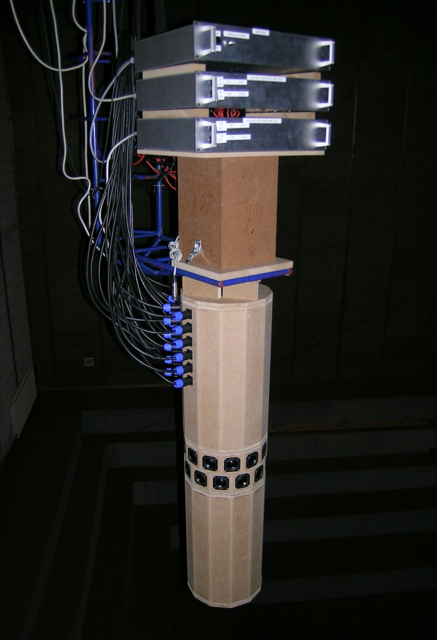
By early 2011, these loudspeakers were built (although not finished…) and ready for measurements and tuning. The photo below shows the “raw” loudspeaker on the crane in the Cube going out to be measured.
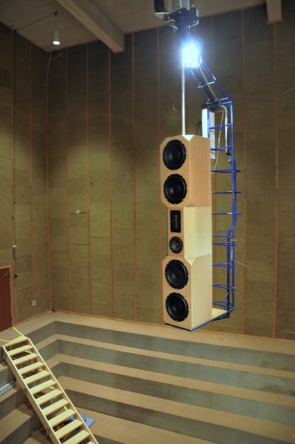
Those loudspeakers lived in Listening Room 1 for about a year. We’re bring people in for a “special demonstration” of a loudspeaker behind the curtain. The general consensus was that the loudspeakers sounded great – but when the curtain was opened, many people started laughing due to the sheer size (and the ugliness of my design, apparently…) of the loudspeakers.
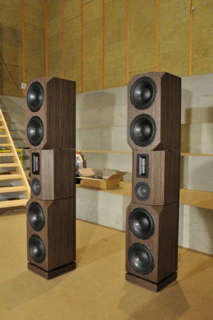
The second “stream” was an idea that was born from Gert Munch’s goal of building a loudspeaker with a smooth power response as well as a flat on-axis magnitude response. The experiment was based on a “normal” two-way loudspeaker that had an additional side-firing dipole on it. The basic idea was that the two-way loudspeaker could be equalised to deliver a flat on-axis response, and the dipole could be used to correct the power response without affecting the on-axis sound (since the on-axis direction is in the “null” of the dipole). For more details about this project, please read this post.
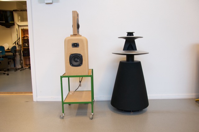
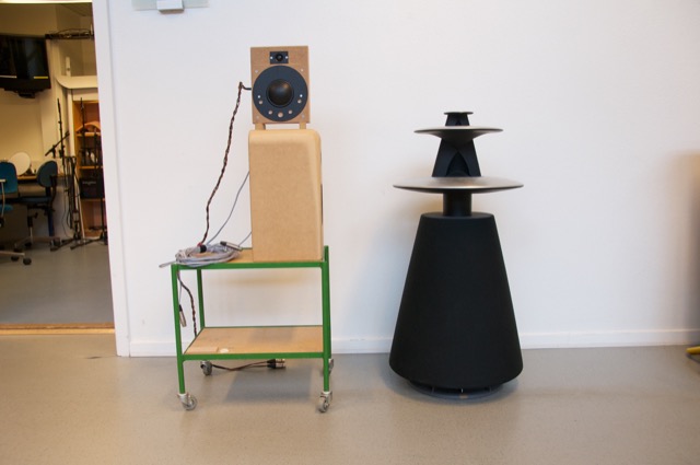
After the “shark fin” experiment, we knew that we wanted to head towards building a loudspeaker with some kind of active directivity control to allow us to determine the amount of energy we sent to the nearby walls. Two members of the Acoustics Department, Gert Munch and Jakob Dyreby, had been collaborating with two graduate students (both of whom started working at B&O after they graduated), Martin Møller and Martin Olsen on exactly this idea. They (with Finn Agerkvist, a professor at DTU) published a scientific paper in 2010 called “Circular Loudspeaker Arrays with Controllable Directivity”. In this paper they showed how a barrel of 24 small loudspeaker drivers (each with its own amplifier and individualised DSP) could be used to steer a beam of sound in any direction in the horizontal plane, with a controlled beam width. (That paper can be purchased from the Audio Engineering Society from here.)
The next step was to start combining these ideas (along with other, more developed technologies such as Thermal Compression Compensation and ABL) into a single loudspeaker. The first version of this was an attempt to reduce the barrel loudspeaker shown in Figure 6 to a reasonable number of loudspeaker drivers. The result is shown below in Figure 7.
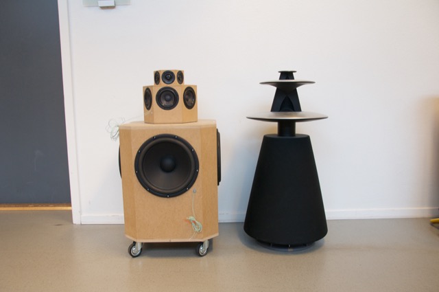
This first prototype had a hexagonal arrangement of tweeters and midranges (6 of each) and a square arrangement of woofers. Each driver had its own DSP and amplification with customised filters to do the “usual” clean-up of magnitude response in addition to the beam steering much like what is described in the AES paper.
Unfortunately, this version was not a success. The basic problem when trying to do directivity control actively is that you need the loudspeaker drivers to be as close together as possible to have control of the beam width in their high-frequency band – but as far apart as possible to be able to control their low-frequency band. In the case of prototype 1, the drivers were simply too far apart to result in an acceptably constant directivity. (In other words, the beam width was different at different frequencies.) So, we had to try to get the drivers closer together.
For the second prototype (shown below in Figure 8, 9, and 10) we decided to try to forget about a steerable beam – and just focus (forgive the pun) on a narrow beam with constant directivity (the same beam width at all frequencies). In addition to this, we experimented with a prototype 8mm supertweeter that would take care of the band from about 15 kHz and up.
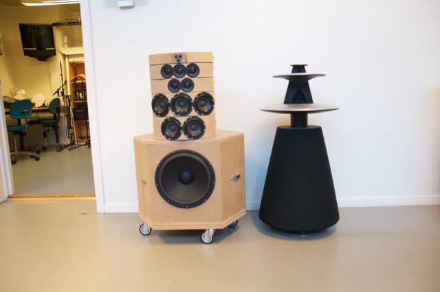
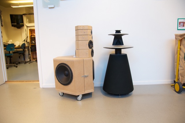
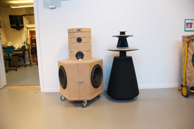
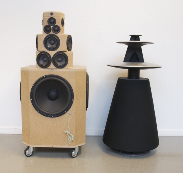
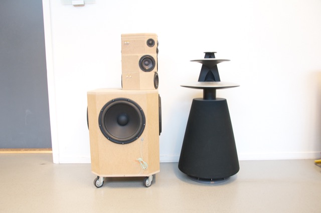
Although Prototype #2 sounded great in the sweet spot, it lacked the versatility of the first prototype. In other words, it was an amazing loudspeaker for a person with one chair and no friends – but it was not really a good loudspeaker for sharing… So, we started working on a third prototype that merged the two concepts – now called “Beam Width Control” and “Beam Direction Control”. The result in shown below in Figures 11, 12, and 13.
As you can see there, the “cluster” of 3 tweeters and 3 midranges comes from prototype 2 – but we re-gained side-firing drivers and rear-firing drivers to be able to steer the sound beam in either of 4 directions. The Beam Width could only be controlled for the front-firing beam, since it is a product of the cluster. You’ll also notice that the super tweeter was still there in this prototype. However, we also changed to a different tweeter and were starting to question whether the extra 8mm driver (and its amplifier, DAC and DSP path) would be necessary.
One thing that any good acoustical engineer knows is that corners cause diffraction. This is well-known at B&O as you can read here. Looking at the enclosure for the midranges and tweeters in the three previous figures, you can see many flat surfaces and corners – which, we assumed, were bad. So, we set about on an informal experiment to find out what would happen if we smoothed out the corners in an effort to reduce diffraction – or at least to change it. This was initially done by applying putty to the MDF enclosures and measuring the off-axis response of the result. One example of this (in progress of bring coated with putty – this was not the final version – it’s just there to show the process) is shown below in Figure 14.
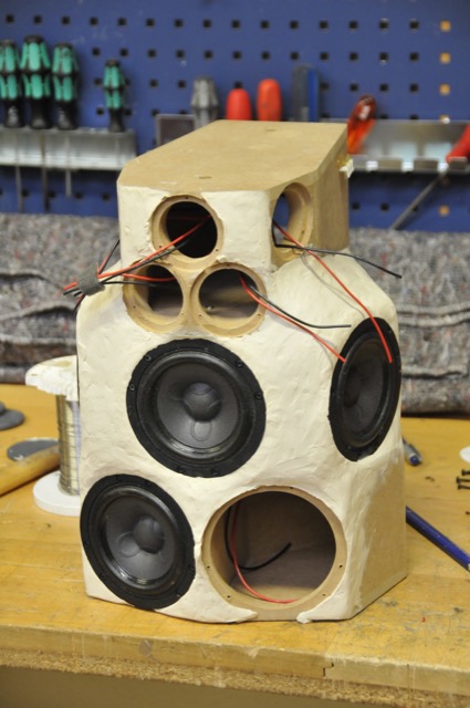
Surprisingly, we found out in these tests that the “smoothing” of the structure around the midranges and tweeters either made no difference or made things worse. So, we continued on, knowing that the final result would be “smoother” anyway…
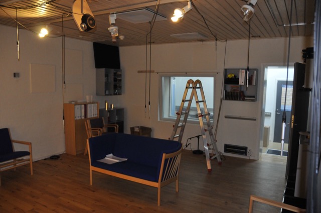
While that work was going on in the Cube, a third “stream” for the project was underway – the development of the Active Room Compensation algorithm. In the early versions, it was called “ASFC” or “Active Sound Field Control” – but as time went on and the algorithm evolved, we changed to a different system and gave it a different name. Photo 15, below, shows the listening room during one of the tests for the original algorithm. I count 9 microphones in there – but there may be more hiding somewhere.
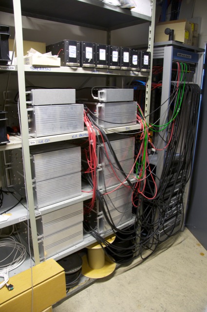
All of the prototypes shown above are just loudspeaker drivers in MDF enclosures. All of the DSP and amplification (in a worst-case, 17 channels in total per loudspeaker) were outside the loudspeakers. In addition, the amplifiers needed active cooling (a fancy way to say “fans”) so they had to be in a different room due to noise. The photo below shows the rack of DSP boxes (on top) and amplifiers (4 channels per box) used for the prototyping.
While this equipment was being used to evaluate and tune the complete prototypes, a parallel project was underway to find out whether we could customise the amplifiers to optimise their behaviour for the use. For example, if you know that an amplifier will only be used for a midrange driver, then it doesn’t need to behave the same as if it were being used for a full-range loudspeaker. I’ll describe that development procedure in a future blog posting, since it’s interesting enough to deserve its own story.
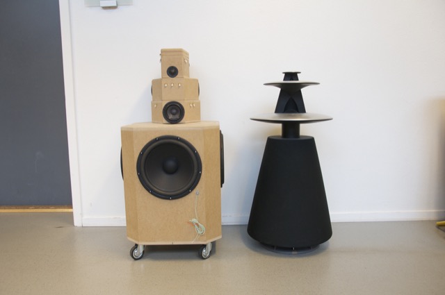
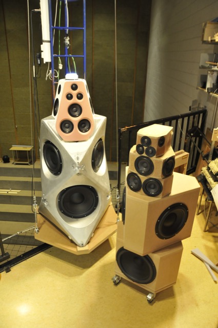
Finally, we were at a point where we built a first prototype of the “real thing”. This was hand-built using 3D-printed parts and a lot of time and effort by a lot of people. The first example of this stage is shown below on the crane in the Cube, sitting next to Prototype #4 for comparison. Notice that, by now, we had decided that the supertweeter was unnecessary, since the Scan-Speak tweeter we’re using was reliable up to at least 40 kHz. The only significant difference between the 4th prototype and the mechanical sample is that the wooden version has only one tweeter and one midrange pointing directly backwards. The “real thing” has two, aimed slightly towards the Left Back and Right Back. (See the Technical Sound Guide for more detailed information about this.)
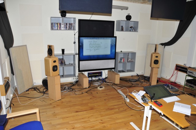
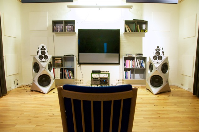
Once the measurement of the first mechanical samples were done and the correct filters programmed into it, it was time to move a pair into the listening room to see (or, more importantly, to hear) if they performed the same as the wooden prototypes. The first setup of device numbers 2 and 3 (the first one stayed with the electronics team for testing) in Listening Room 1 in Struer is shown below in Figure 18. For reference, the room is 6 m deep x 5 m wide – and that’s a 55″ BeoVision 11 on the wall.
When we did the measurements on the samples shown in Figure 18 – both in the Cube and in the listening room, we could see that there was an unusual (and unexpected) dip in the on-axis magnitude response of about 1 dB at around 8o0 Hz. Unfortunately, it did’t seem to be easily correctable using filtering in the DSP, which meant that it was probably the result of a reflection somewhere off the loudspeaker, cancelling the direct sound at the listening position. After a day or two of playing with putty placed in various locations around the loudspeaker, we found that the problem was caused by a reflection off the “shelf” just below the face of the top unit. That can be seen in Figure 19, below.
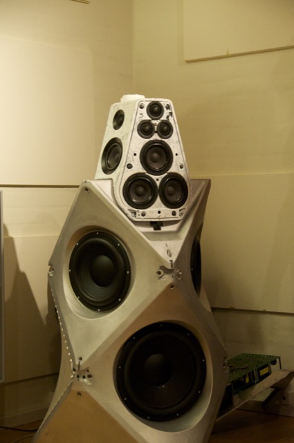
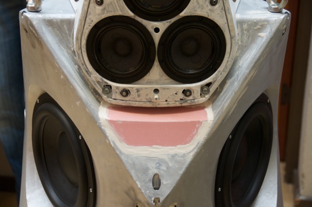
The way to correct this problem was to bring the height of the shelf up, which also meant that it was closer to the face of the top cluster. (Note that the front panel is missing in Figures 19 and 20 – the actual face is the pink panel seen in Figure 22.) This fixed the problem, but it meant changing the mould for the aluminium enclosure. In the meantime, while that change was happening, we were able to 3D-print an insert of the same shape that could be used for the listening reference pair of loudspeakers. This meant that we didn’t have to wait for the new aluminium versions to start tuning.
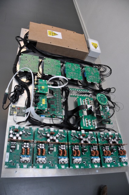
Of course, the electronics team developed their components on a test bench, piece by piece. Eventually, all of those pieces came together into a single unit (minus the loudspeaker drivers and enclosures) which could be used for testing and software development. An example of one of those test boards (actually, the first one of its kind to be made – and one of the few with all of the amplifiers attached…) is shown below in Figure 21.
I’ll probably show some better photos of the DSP board in a later posting.
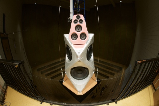
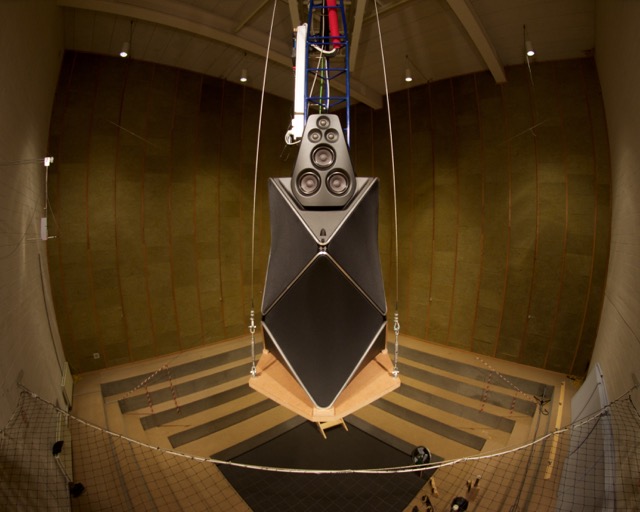
Finally, everything came together into a product that, acoustically and electrically, was identical to the production model. This is the version that we use for sound design. It’s shown (about to go out into the Cube for yet another round of measurements) in Figures 22 and 23, below.
Millemissen says:
Now we finally see all the pieces of your previous B&O Tech articles come together.
Thanks for the overview.
And bravo!!!
geoff says:
Thanks! It’s been years in the making – and there’s still work to be done. But today is definitely a day of celebration around here! :-)
Cheers
-geoff
The Dandy Domain says:
What a great story!
Looking forward to getting closer to the beast and thanks for sharing all these insights.
Hadi says:
kudos! Great piece of dream.
I’m Speechless.
Nicolas says:
Well….nice work guys, but a company like B&O is in a deep crissis and then you make a 70.000€ speakers!?!
Use your knowladge on Beo Play, and send some mo ey to your shareholders who atr paying your jobs. B&O is still in 80’s and make ugly products.
geoff says:
Hi Nicolas,
Thanks for your comments. I’ll pass your comments on to those who investigate the business cases for each of our products.
Cheers
-geoff
geoff says:
Hi Hadi,
Thanks!
Cheers
-geoff
Steve Marriott says:
Hi Geoff, many thanks for the insight into the design process behind these stunning speakers – I will be very interested to hear them in person once they have been launched.
Keep up the good work!
Kind regards, Steve, Sounds Heavenly Cables
geoff says:
Hi Steve,
Thanks!
Cheers
-geoff
Sam says:
Hi Geoff,
Absolutely incredible acoustical and aesthetic design congratulations and creating such a beautiful product!
Just wondering how do you make sure that the rear facing drivers don’t interfere with the intergrity front firing sound and clutter the sound?
Can’t wait to hear them in person!
Thanks and good luck for the future!
Sam Smith
Dave Farr says:
I don’t claim to understand most of what you have done to create these speakers but can only state my admiration for your skills, creativity and enthusiasm – all of the team involved. Whilst out of reach for mortals such as I, these should put B&O back on the map and at least silence some of the doubters. 8200 Watts will silence (and deafen) anyone! Thanks for another fascinating piece Geoff. I also assume that some of these technologies will make their way to some smaller and more affordable speakers soon, but of course, you cannot confirm or deny that.
Ole Larsen says:
Great post Geoff!
Finally all these strange “projects” in the last many years end out with a real statement product we are all so proud of – amazing job you guys!
geoff says:
Hi Sam,
The point of the rear-facing drivers is to interfere with the front-firing drivers. However, this is done in a very controlled fashion using an individual FIR filter customised for each driver. Consequently, at one frequency, the back drivers may be cancelling the front in a given direction whereas at another frequency, they are “helping”. The magnitude and phase responses of the filters are the result of the measurements of the drivers in their locations, and an optimisation algorithm designed to find the best possible solution to the target of a given beam width.
Cheers
-geoff
Radulescu Paul says:
Hello there!
I see that in your prototype there are one 13″ and 3 10″ bass drivers, but on the official site, on specifications of the final product, it says they are 1*10″ and 3*8″. Can you please tell me/us why not stick with those powerfull and large drivers?
Thank you
geoff says:
Hi,
The Scan-Speak Revelator 32W/4878T00 is a 13″ woofer – but its effective diameter is 260 mm, which converts to approximately 10″. (The Discovery 26W dimensions have a similar difference…) This difference is caused by the way the driver is measured – specifically, where on the diaphragm the measurement is taken for the “effective diameter” vs. the usual classification (i.e. 13″).
You can also see a more complete version of the specifications (which are not yet entirely complete, since we’re still in the final tuning process) in the Technical Sound Guide, downloadable from here.
Cheers
-geoff
Morten Bache says:
Hi Geoff,
Great piece, very inspiring. I have to admit I was very skeptical when I saw the press release, but reading your behind the scene insight really made it clear how much research and engineering there is behind the new speakers. So I’m not an acoustic researcher or anything, just an average user of high end hifi, but is this speaker, or type of speaker, totally new and unique or are there other types of similar ideas out there? I remember the digital room correction from TACT essentially trying to solve the same issue, but on the speaker side are any other companies working in this direction?
I guess the “listening while cleaning” debate is misunderstood, but maybe we don’t need to spell that out here. I think the concept of abandoning “one chair-no friends” type of speakers is much more precise.
Cheers,
Morten
PS When will mere mortals like most of us be able to listen to these speakers?
geoff says:
Hi Morten,
It’s a difficult question to answer.
There are other loudspeakers that address the “problem” of sidewall reflection through directivity. Typically a REAL dipole loudspeaker will have a null at 90º off-axis to the front, which helps to attenuate the sidewall reflections. However, a dipole loudspeaker is extremely sensitive to placement within a room, particularly with respect to the proximity of the wall behind the loudspeaker. Some large-scale sound reinforcement systems use multiple loudspeakers to control vertical directivity (for example, in football stadia), but these are typically set-and-forget where they’re aimed at a portion of the crowd and then left forever. The Beam Width Control in BeoLab 90 gives you the option to have the sidewall control of the dipoles without the sensitivity to room placement, with a “surgical” version of the directivity control of the large PA systems. Of course, it also gives you the option to change the directivity easily, without having to swap loudspeakers.
One way that I think of the combination of Beam Width Control and Beam Direction Control is that the BeoLab 90 is actually 7 different loudspeakers (3 widths and 5 directions with one overlap between the two). The bad thing for me is that this means that I have to do 7 different sound designs – one for each mode, but that’s my day job… :-)
There are many room compensation systems on the market, but to my knowledge, none gives you the flexibility of Active Room Compensation.
I hope that answers your first question. I can’t currently answer the last one…
Cheers
-geoff
Søren Andersen says:
hi Geoff,
You have really gone all in with this speaker :-) Nice work. Do you still compare all the speakers with that little metalspeaker you brought from Canada when you first started at B&O?
Cheers
Søren
Morten Bache says:
Hi Geoff,
Thanks for the explanation, I think I have an idea about what you do. So 7 “speakers” are needed for this to work “perfectly”, as I guess was the aim with BeoLab 90, so the widths and the directions sort of mix properly. It will be really interesting to see how you can manage to maintain somewhat the experience but in a more low-key and inexpensive design. I could imagine I would be happy to settle with a line of sweet spots, imagining one man and some friends on a couch :-)
Probably this could be similar amounts of research and engineering at the end of the day :-)
Cheers,
Morten
Gabriel Lundmark says:
Wow, your prototypes look like the finished products other companies put out.
And Nicholas, don’t be a douche. Your imprecise comments show that you’re clearly not the target audience for these speakers. Good thing they got Beoplay too then.
In my opinion, this is *exactly* what B&O should be doing.
Claus Mikkelsen says:
Tremendous effort. Really exiting insight. Thanks for sharing. So looking forward to hear the result of your effort. All the best.
Cheers Claus.
Peter Pedersen says:
Hi,
What were your criteria for selecting the speaker units you used? Which specifications did you deem the most important, and why? Did you prefer certain technologies over others – materials, shape, etc? To what extent was price an issue?
Sorry about my inquisitiveness, but I’m trying to drill my way into the more “technical” part of your mind / considerations :-)
Regards, Peter
geoff says:
Hi Peter,
I’m afraid that I can only partially answer your question. The reason for this is that I was not the person on the team who selected the loudspeaker drivers – so there are some criteria that I know nothing about. However, I can make a couple of comments that might offer some insights.
The one, most important thing that I can say is that there is no one aspect of any loudspeaker or component that makes it good. There may be one aspect that makes it bad – but, as with any system, it’s the combination of components that results in a higher quality. The analogy I often use is that of a Ferrari and a racing bicycle – neither of them goes fast just because of a single thing. If you put bicycle tires on a Ferrari, you won’t get far very quickly. If you put Ferrari tires on a bicycle, it won’t go fast. The “magic” is in the combination of the appropriate components, all used in correct alignment.
That said:
One intriguing aspect of the Illuminator series from Scan-Speak is its Bl curve resulting from its motor. The underhung motor system (meaning that the voice coil is small relative to the size of the magnetic field in which it sits) ensures that the motor has control of the driver for an extended excursion. In addition, there is very, very little, (if any) artefacts in the magnitude response caused by edge reflections on the diaphragm. Finally, the off-axis response behaves very nicely – which was an important factor for the BeoLab 90.
As I mentioned in the posting above, we experimented with different tweeters (including some others that I did not mention there). If we stick to dome tweeters, there is quite a debate regarding soft domes vs. hard domes. I don’t pretend to know enough to enlighten anyone on this debate. However, I will say that my experience as a subject in many blind listening tests on various types of tweeters indicates that, unless you (at a very minimum) equalise for the on-axis magnitude response differences between different tweeters, their linear response differences alone will result in very distracting preferences. Since B&O uses DSP to equalise all of our drivers, our primary concerns are linearity over a wide SPL range and directivity. Magnitude response differences can be corrected in the processing. Linearity and directivity cannot.
As far as I know, the BeoLab 90 woofers were chosen using the same philosophy – linearity and directivity. However, the frequency-dependent maximum SPL was, of course, also a consideration for the woofers. This is partially because we are pushing them down to about 10 Hz (although this low-frequency cutoff has not yet been finalised – it is certainly subject to change). It is also because we are, at some frequency bands and in some Beam Widths, using the 10″ woofers to actively absorb energy from the 13″ driver. Consequently, we need the entire system to “behave” (in other words, it has to be as linear as possible) to ensure that we maintain control of the directivity.
I hope that this is enough information to adequately answer your question.
Cheers
– geoff
Fredrik Lindqvist says:
Very intresting to se the progress you have dun Geoff!
This must be one of your life’s achievement, and it looks almost like NASA developed the product for their next Mars expedition. ;)
Do you belive this is the best sounding speaker in the world and can you describe their sound characteristics, and how do you feel their sound comparing to conventional passive High-End speakers like Wilson Audio , MBL Reference 101 , Focal Utopia Grande ?
Have a nice evening Geoff!
Best Regards
Fredrik Lindqvist
Fredrik Lindqvist says:
PS I forgot to ask whats the max SPL from 1 meter with two speakers of BeoLab 90 ?
Best Regards
Fredrik Lindqvist
Michael says:
Everything I really wanted to say has already been said above, so I just salute you all for one innovative, good-looking, massive project!. I my mind this project puts B&O back where they belong, leaving the mid-fi area and moving into high-end – with typical B&O touch. well done and keep partying!
Gabriel Lundmark says:
Please don’t ever leave the mid-end, though. I still love my Beolab 9s and I’m not sure I’ll ever have enough money to spend on better speakers. Well, I guess I would, but I am extremely happy with the 9s so I really don’t see the point.
geoff says:
Hi Fredrik,
It’s unfair of me to comment on the loudspeakers of our direct competitors and how they compare to B&O loudspeakers – so I almost never do.
I will say, however, that as part of the development process of the BeoLab 90’s, we auditioned a wide range of high-end loudspeakers. Each of them had some good aspect – for one it was imaging, for another it was midrange, for another it was temporal precision, for yet another it was a weird ability to sound like itself regardless of the room it was in, and so on… Our goal with BeoLab 90 was to take the attributes we liked from each loudspeaker we listened to, and assemble those into one product. In my (admittedly biased) opinion, we succeeded.
Cheers
-geoff
P.S. regarding your SPL question – the answer is “we don’t know yet”. The tuning process of the BeoLab 90 is not yet finished – which is why some of the specifications available on-line say “TBD”. We’ll make those available as soon as we have them.
Bart De Bie says:
Hi Geoff,
Nice work on the new speakers, they are amazing!
Now I have a couple of questions?
Normally in a home theatre system the center channel speaker should be the biggest one because 75% of the movie goes through the center channel, how do you in this respect think 6 beolab 90 speakers will cope in conjunction with the center speaker of the beovision avant?
Second question.
Does the Active Room Compensation technology work in a similar fashion as the beolab 5 with build in microphones and test signal?
Third question.
Will there be a beosound 9000 system with dab radio, sa-cd, apple airplay and wisa wireless sound to serve as a fornt end to the speakers (one can only dream, you know)?
Fourth question.
Will there be a rack mountable stereo/surround audio interface with wisa wireless sound so you can integrate them into a recording studio to serve as monitors for mixing and mastering (some more dreaming)?
Fifth question.
When can we go out to our dealer and buy a pair?
Again, they look amazing, can’t wait to hear them in real life!
Kind regards
Bart
Duke LeJeune says:
Very interesting and innovative approach to radiation pattern control, tailoring the signal to the side-firing drivers to either narrow or widen the primary lobe, as needed! That’s probably just the tip of the iceberg, but I’m very impressed.
Can you give us an idea of what shape radiation pattern you have achieved, and how that translates into an improvement over the already very impressive pattern of the Beolab 5?
Thanks!
geoff says:
Hi Duke,
The measurements of the directivity patterns can be seen in the BeoLab 90 Technical Sound Guide or at this posting.
Cheers
-geoff
geoff says:
Hi Bart,
Thanks for the compliment!
To respond to your questions:
1. It’s a little misleading to say that 75% of the audio in a movie comes from the centre channel. Nearly all of the dialogue comes from the centre channel, but this is different. The BeoVision Avant will automatically bass-manage to the BeoLab 90’s, just like it would do to any other BeoLab loudspeaker that has a higher bass capability. So, you only need to worry about signals above (approximately 120 Hz), and only at listening levels beyond what the Avant can achieve… Whether this is happening with BeoLab 90’s or BeoLab 5’s or another loudspeaker doesn’t really change the situation – or, more correctly stated, the situation is not different with BeoLab 90 than another loudspeaker model.
2. Yes, and No. Some of the answer to this question can be found here and here. The rest of the answer (specifically about BeoLab 90’s multichannel component of its room compensation algorithm) is coming in a future blog posting.
3. I cannot comment on products that are not in the current or past portfolio. Sorry.
4. I cannot comment on products that are not in the current or past portfolio. Sorry.
5. This depends partly on your dealer. You’d have to ask them directly about this. Sorry.
They sound amazing too (although I’m admittedly biased…) :-)
Cheers
-geoff
Michael says:
Wow!
Thats a piece of art and tech :)
Nicolai Hald says:
Just a small input to your day to give you an even larger smile than you had the day I met you. You changed my day from being a downer to an amazing day, just with the 30 minutes you were telling us students about acoustics. You are such an amazing man with all you have done both at B&O i Struer, but also in everything else. You are so near as possible, of being the definition of the ultimate man in a sound company. You are just amazing. Wow.
Hope you’ll read this once, and give you a smile.
On behalf of the HTX students – Thank you!
And Merry Christmas!
geoff says:
Hi Nicolai,
How do I respond to that!? Thank you VERY much for your kind words. I’m glad to hear that you and your colleagues enjoyed your visit to Struer. I have to admit that I’m surprised that a lecture in acoustics could turn someone’s day around – but I’m glad it did.
cheers
-geoff
Bart De Bie says:
I totally agree with the last sentence of Nicolai Hald’s post.
You are like the ‘Manuel Garcia or Francesco Lamperti’ of acoustical design & research.
Merry Christmas (for the diehard fans read: b&o-mas) to you, your family and your colleagues at b&o
Bart
GB says:
I’m very interested owning beo 90. So far it is the best speaker system I have hear for home without non proffesionals room treatment tuning…etc. I guest there are very sophisticated reflection cancelation logarithm programming and it is not 100% completed. So for the early models, how can customer insure that it will not be replace by upgrade or new model?
geoff says:
Hi,
Thanks for the kind words about the audio quality of the BeoLab 90!
Of course, I cannot comment on anything outside of the current product portfolio so, unfortunately, I cannot answer your question. However, you are correct in stating that the software for the BeoLab 90 is not 100% completed. There are a number of software updates coming in the future to bring its feature list up to that described in its manuals.
Cheers
-Geoff
Radulescu Paul-Mircea says:
Hi Geoff,
Thank you very much for your reply for my question about the driver’s dimensions.
Now I have another concern… So, in the front side of the speakers i can se that there are 3 mids and 3 tweeters. My concern is how you manage to avoid comb filtering and interferences at mid and high frequencies? If one wants to couple two or more speakers without interferences, one must have the sound sources within aprox. 1/4 of the smallest wavelenght they will play from each other. That would be 4 mm at 20000 Hz for the tweeters and 40 mm at 2000 Hz. So the midrange drivers and the tweeters would have large comb filterring in their operating band
geoff says:
Hi. your math would be correct if all drivers were playing the same signals – but in the Beolab 90, this is not the case. The filtering in the DSP ensures that no two drivers are playing the same signal at any frequency. So, the rule of thumb usually applied to drivers in parallel don’t apply.
cheers
– geoff
Radulescu Paul says:
Thank you for your answer.
So, from What I understand, even in the front face, where there are 3 mids and 3 tweeters, none of them are working in paralel. Good thinking. Probably in High power, omni mode they do, but in that case it would be used at a party and no one would care :)
Radulescu Paul says:
By the wat.. Why Heliox? :D
geoff says:
Hi,
The reason for choosing the Heliox for the woofers was that we needed an amplifier that had a different relationship between the available voltage and current than the ICEPower.
For example, if you want a 1000 W, you can get this with 10 V and 100 Amps, or 100 V and 10 Amps – or something else…
Cheers
-geoff
Michael says:
Hi, I heard a demo of the Beolab 90 the other day and I was deeply impressed – you guys have done superb job! Two things really stood out -first the bottom octaves; incredibly deep, well integrated with the other registers, and incredibly nuanced. Secondly, imaging; the recording for Concertgebouw was noting short of ridiculous! Not only did the speakers reproduce instruments realistically, it also did paint the scene in three dimensions. Now, this I have heard before. But, what I never heard before was the placement of the microphones. We were discussion from what position we were listening – which to me was a new level. Amazing job!!
The only question mark is that maybe I perceived it a tad grainy and maybe, just maybe I would have wished for the feeling of more weightlessness in the treble.. Here I am comparing with French electronics – the Devilaet system and my ceramic accuton drivers. Don’t know if I am totally lost – just wanted to provide my 5 cents! Cheers!
geoff says:
Hi Michael,
Thanks for your comments!
I would recommend that you not make any final judgements on the tonal balance – particularly the treble – until the final software version is released. We’re still making the final adjustments on the sound design (a.k.a. “tuning”) – and the Active Room Compensation is not yet implemented.
cheers
-geoff
Scott says:
Well. What can I say? I was invited to a demo of the beolab 90 speakers. 3 days later I have bought a pair. These will be my 5th pair of B&Ø speakers. I guess I am a fan. I will have a while to wait for my order to be filled, but I can be patient.
Listening to the speakers on three different days, playing a variety of my music and the store’s convinced me that these are the best I will hear. There is a new dimension (for me) of the sound. A depth of placement for the instruments and voices, not merely a direction.
Best of all, my wife liked what she heard so much that she convinced me to buy them.
Thanks for all the work that has gone into making these a reality.
geoff says:
Hi Scott,
This is great to read – you made my day! Please give my greetings to your wife – and my compliments for her excellent decision-making abilities. :-)
Cheers
-geoff
Gary Eickmeier says:
Geoff – I don’t think as much of your project as the others here. I have not heard the 90s, but I can imagine what they sound like from your description of the radiation pattern. Your problem is that you are operating with a stereo theory that believes that the imaging is all caused by the direct sound. But live sound consists of a small amount of direct sound followed by a greater amount of early reflected and then the full reverberant field. Stereo is a field-type system, not a head-related system like binaural. The answer is to study the image model of live sound and try to mimic that with the radiation pattern of the speakers combined with the placement of the speakers in the room w respect to the walls around them. With more energy cast in the reflecting direction you can set up a huge soundstage that occupies the entire front of the room rather than just speaker to speaker. You can also incorporate distance/ intensity trading to keep center imaging stable as you go across the room (less of a sweet spot).
If you are interested in more about this, please write to me in email. I would also like to know if there is any place in Florida where I might listen to the 90s.
geoff says:
Hi Gary,
We both agree and disagree.
I’ll find out where you can hear a pair of Beolab 90’s in Florida – but I suspect that if you prefer loudspeakers with a wide directivity, you should either make sure that you hear them in “Wide” mode – or you should wait until the “Omni” mode is also implemented in the software. I’ll send you an email in a couple of weeks.
Cheers
-geoff
geoff says:
Hi again Gary,
Sorry it took a while to find the information for you. I was travelling all last week. The Bang & Olufsen store in South Miami has a pair on display that you are welcome to audition. The address is
Bang & Olufsen South Miami
7295 SW 57th Ave
South Miami, FL 33143
Cheers
-geoff