#34 in a series of articles about the technology behind Bang & Olufsen loudspeakers
A little background:
Distance Perception in “Real Life”
Go to the middle of a snow-covered frozen lake with a loudspeaker, a chair, and a friend. Sit on the chair, close your eyes and get your friend to place the loudspeaker some distance from you. Keep your eyes closed, play some sounds out of the loudspeaker and try to estimate how far away it is. You will be wrong (unless you’re VERY lucky). Why? It’s because, in real life with real sources in real spaces, distance information (in other words, the information that tells you how far away a sound source is) comes mainly from the relationship between the direct sound and the early reflections that come at you horizontally. If you get the direct sound only, then you get no distance information. Add the early reflections and you can very easily tell how far away it is. If you’re interested in digging into this on a more geeky level, this report is a good starting point.
A little more background:
Distance perception in a recording
Recording Studios vs. Living Rooms
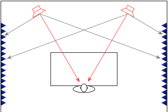
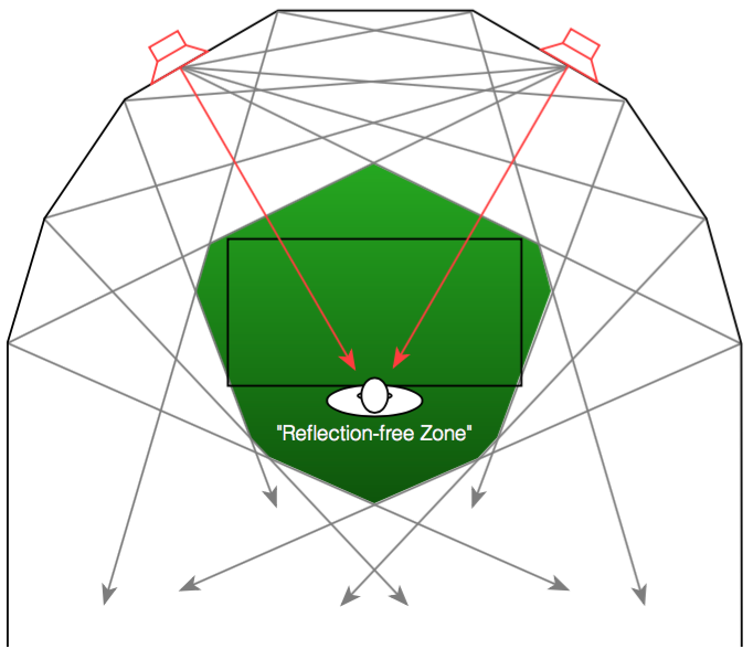
When a recording engineer makes a recording in a well-designed studio, he or she is sitting not only in a carefully-designed acoustical space, but a very special area within that space. In many recording studios, there is an area behind the mixing console where there are no (or at least almost no) reflections from the sidewalls . This is accomplished either by putting acoustically absorptive materials on the walls to soak up the sound so it cannot reflect (as shown in Figure 1), or to angle the walls so that the reflections are directed away from the listening position (as shown in Figure 2).
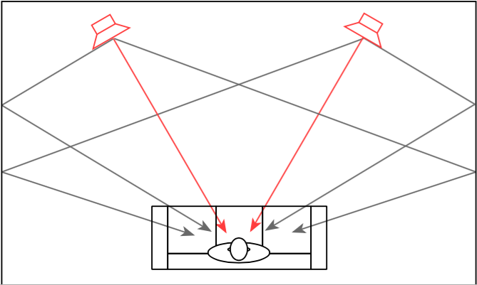
Both of these are significantly different from what happens in a typical domestic listening room (in other words, your living room) where the walls on either side of the listening position are usually acoustically reflective, as is shown in Figure 3.
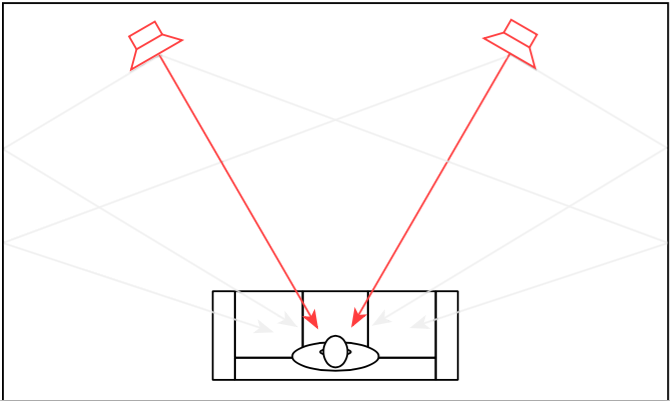
In order to get the same acoustical behaviour at the listening position in your living room that the recording engineer had in the studio, we will have to reduce the amount of energy that is reflected off the side walls. If we do not want to change the room, one way to do this is to change the behaviour of the loudspeaker by focusing the beam of sound so that it stays directed at the listening position, but it sends less sound to the sides, towards the walls, as is shown in Figure 4.
So, if you could reduce the width of the beam of sound directed out the front of the loudspeaker to be narrower to reduce the level of sidewall reflections, you would get a more accurate representation of the sound the recording engineer heard when the recording was made. This is because, although you still have sidewalls that are reflective, there is less energy going towards them that will reflect to the listening position.
However, if you’re sharing your music with friends or family, depending on where people are sitting, the beam may be too narrow to ensure that everyone has the same experience. In this case, it may be desirable to make the loudspeaker’s sound beam wider. Of course, this can be extended to its extreme where the loudspeaker’s beam width is extended to radiate sound in all directions equally. This may be a good setting for cases where you have many people moving around the listening space, as may be the case at a party, for example.
For the past 5 or 6 years, we in the acoustics department at Bang & Olufsen have been working on a loudspeaker technology that allows us to change this radiation pattern using a system we call Beam Width Control. Using lots of DSP power, racks of amplifiers, and loudspeaker drivers, we are able to not only create the beam width that we want (or switch on-the-fly between different beam widths), but we can do so over a wide frequency range. This allows us to listen to the results, and design the directivity pattern of a loudspeaker, just as we currently design its timbral characteristics by sculpting its magnitude response. This means that we can not only decide how a loudspeaker “sounds” – but how it represents the spatial properties of the recording.
What does Beam Width Control do?
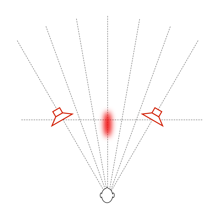
Let’s start by taking a simple recording – Susanne Vega singing “Tom’s Diner”. This is a song that consists only of a fairly dryly-recorded voice without any accompanying instruments. If you play this tune over “normal” multi-way loudspeakers, the distance to the voice can (depending on the specifics of the loudspeakers and the listening room’s reflective surfaces) sound a little odd. As I discussed in more detail in this article, different beam widths (or, if you’re a little geeky – “differences in directivity”) at different frequency bands can cause artefacts like Vega’s “t’s” and “‘s’s” appearing to be closer to you than her vowel sounds, as I have tried to represent in Figure 5.
If you then switch to a loudspeaker with a narrow beam width (such as that shown in the directivity plot in Figure 7 – the beam width is the vertical thickness of the shape in the plot – note that it’s wide in the low frequencies and narrowest at 10,000 Hz), you don’t get much energy reflected off the side walls of the listening room. You should also notice that the contour lines are almost parallel, which means that the same beam width doesn’t change as much with frequency.
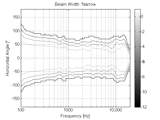
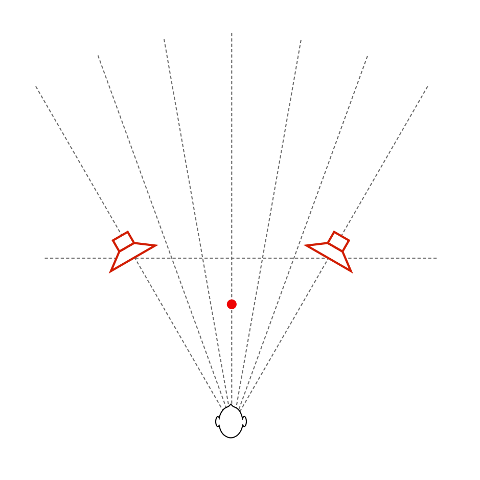
Since there is very little reflected energy in the recording itself, the result is that the voice seems to float in space as a pinpoint, roughly half-way between the listening position and the loudspeakers – much as was the case of the sound of your friend on the snow-covered lake. In addition, as you can see in Figure 7, the beam width of the loudspeaker’s radiation is almost the same at all frequencies – which means that, not only does Vega’s voice float in a location between you and the loudspeakers, but all frequency bands of her voice appear to be the same distance from you. This is represented in Figure 8.
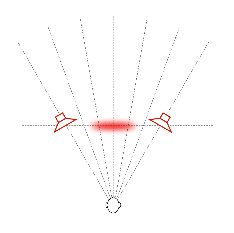
If we then switch to a completely different beam width that sends sound in all directions, making a kind of omnidirectional loudspeaker (with a directivity response as is shown in Figure 9), then there are at least three significant changes in the perceived sound. (If you’re familiar with such plots, you’ll be able to see the “lobing” and diffraction caused by various things, including the hard corners on our MDF loudspeaker enclosures. See this article for more information about this little issue… )
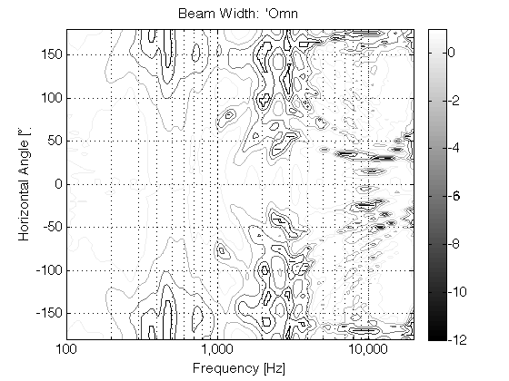
The first big change is that the timbre of the voice is considerably different – particularly in the mid-range (although you could easily argue that this particular recording only has mid-range…). This is caused by the “addition” of reflections from the listening room’s walls at the listening position (since we’re now sending more energy towards the room boundaries). The second change is in the apparent distance to the voice. It now appears to be floating at a distance that is the same as the distance to the loudspeakers from the listening position. (In other words, she moved away from you…). The third change is in the apparent width of the phantom image – it becomes much wider and “fuzzier” – like a slightly wide cloud floating between the loudspeakers (instead of a pin-point location). The total result is represented in Figure 10, below.
All three of these artefacts are the result of the increased energy from the wall reflections.
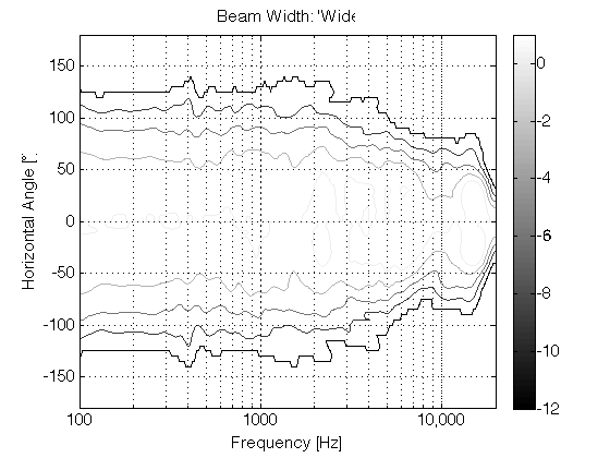
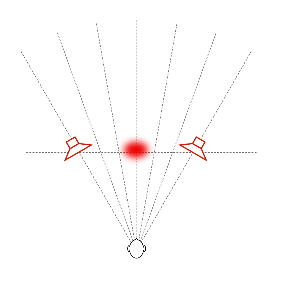
Of course, we don’t need to go from a very narrow to an omnidirectional beam width. We could find a “middle ground” – similar to the 180º beam width of BeoLab 5 and call that “wide”. The result of this is shown in Figures 11 and 12, with a measurement of the BeoLab 5’s directivity shown for comparison in Figure 13.
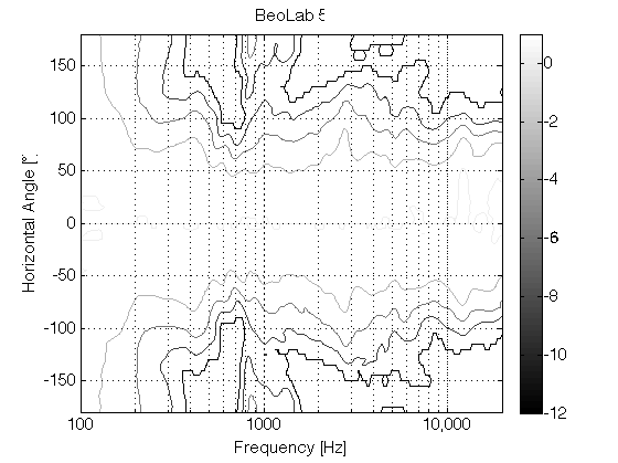
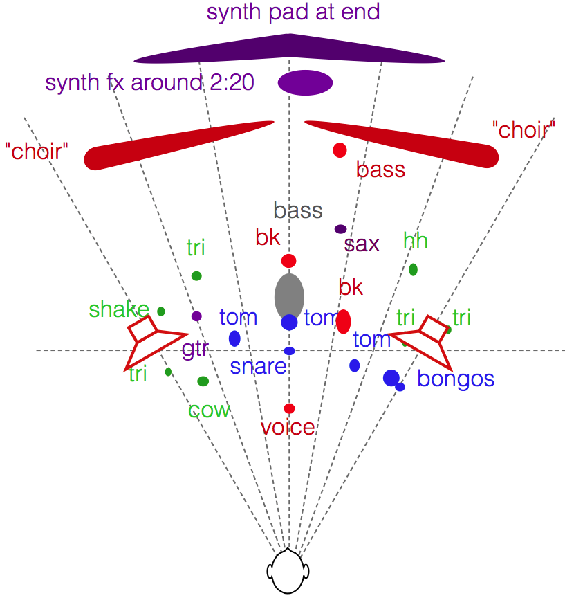
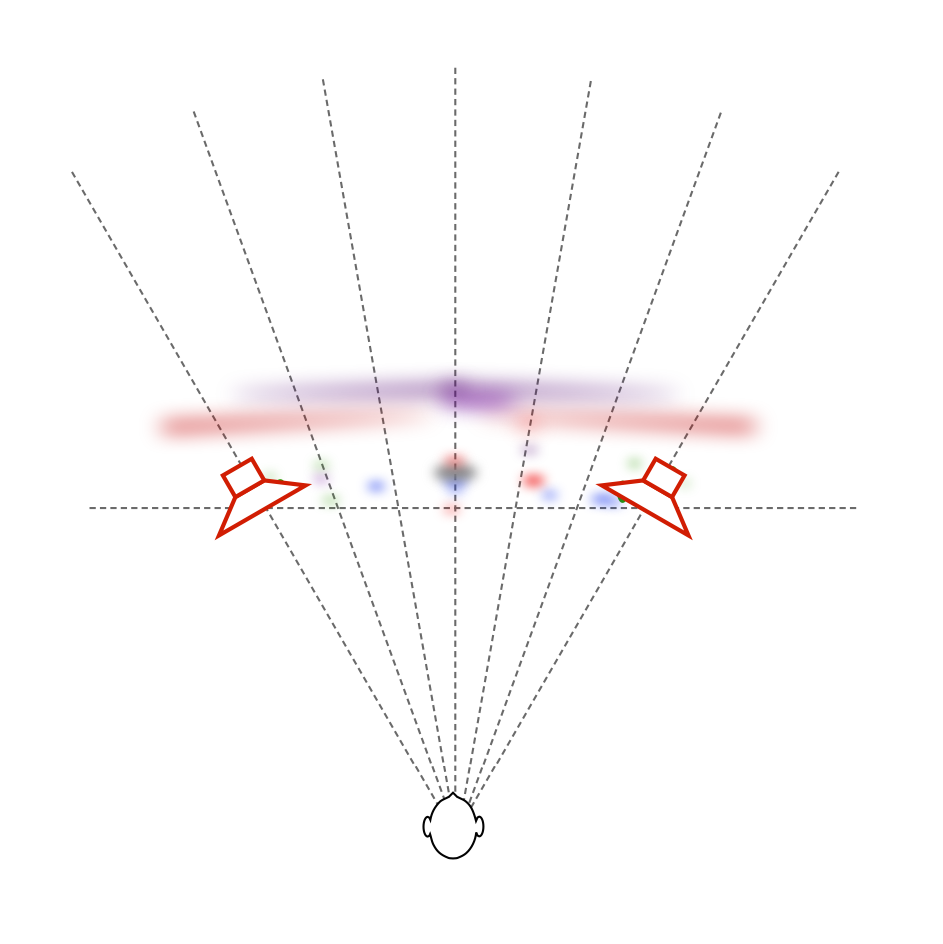
If we do the same comparison using a more complex mix (say, Jennifer Warnes singing “Bird on a Wire” for example) the difference in the spatial representation is something like that which is shown in Figures 14 and 15. (Compare these to the map shown in this article.) Please note that these are merely an “artist’s rendition” of the effect and should not be taken as precise representations of the perceived spatial representation of the mixes. Actual results will certainly vary from listener to listener, room to room, and with changes in loudspeaker placement relative to room boundaries.
Of course, everything I’ve said above assumes that you’re sitting in the “sweet spot” – a location equidistant to the two loudspeakers at which both loudspeakers are aimed. If you’re not, then the perceived differences between the “narrow” and “omni” beam widths will be very different… This is because you’re sitting outside the narrow beam, so, for starters, the direct sound from the loudspeakers in omni mode will be louder than when they’re in narrow mode. In an extreme case, if you’re in “narrow” mode, with the loudspeaker pointing at the wall instead of the listening position, then the reflection will be louder than the direct sound – but now I’m getting pedantic.
Wrapping up…
The idea here is that we’re experimenting on building a loudspeaker that can deliver a narrow beam width so that, if you’re like me – the kind of person who has one chair and no friends, and you know what a “stereo sweet spot” is, then you can sit in that chair and hear the same spatial representation that the recording engineer heard in the recording studio (without having to make changes to your living room’s acoustical treatment). However, if you do happen to have some friends visiting, you have the option of switching over to a wider beam width so that everyone shares a more similar experience. It won’t sound as good (whatever that might mean to you…) in the sweet spot, but it might sound better if you’re somewhere else. Similarly, if you take that to an extreme and have a LOT of friends over, you can use the “omni” beam width and get a more even distribution of background music throughout the room.
For more information on Beam Width Control
Shark Fins and the birth of Beam Width Control
Post-script
For an outsider’s view, please see the following…
“Ny lydteknikk fra Bang & Olufsen” – Lyd & Bilde (Norway)
Stereophile magazine (October 2015, Print edition) did an article on their experiences hearing the prototypes as well.
“BeoLab 90: B&O laver banebrydende højttaler” – Lyd & Bilde (Norway)
Karel Uyttendaele says:
Sooo… :-) We’ll see this later this year in the next gen (BL5 replacement?) speaker :-)
Millemissen says:
In the article in from Lyd & Bilde the setup is described as ‘ via en Auralic Aries musikkspiller og Teac UD-501 DAC’.
Please allow me the question: why not use your own BSys4/audioengine as the source system?
Greetings
MM
geoff says:
hi MM,
There are two main reasons. The first is that the Auralic/Teac combination can play DSD files. The second is that we’re always testing non-B&O equipment to check compatibility.
cheers
-geoff
Yannick Adriaenssens says:
Hi Geoff
I could be the person who has only one chair and one friend, so I will be happy with a speaker with a narrow beam. But I also could be a person with a lot of friends who likes a width beam…
So my question is: is there a possibility to change the settings of a b&o speaker to change the beam width? For example the beolab 3? Because you don’t know who will buy your speaker.
Thanks in advance
Yannick
geoff says:
hi Yannick.
The only way to change the beam width on a conventional loudspeaker such as a BeoLab 3 would be to change its physical shape.
cheers
– geoff
Ronald says:
Has anything been done to optimise time domain behaviour in this extensive DSP effort?
I’d love to see impulse and STEP response of this monster. Very intriguing speaker, you must love your job! I know I would…
geoff says:
Hi Ronald,
The time response of our loudspeakers is one of the basic aspects that we always worry about. I’ll probably put the impulse and step responses of the BeoLab 90 here on this site when we have them available. They aren’t finished yet, since we’re still in the process of tuning the loudspeaker.
Cheers
– geoff
Anders says:
“distance perception in real life”
in that paragraph the link to “this report” seems to be down, any chance it could be updated? Cheers
geoff says:
Hi Anders,
Weird. It works for me. It’s a link to a paper called “PSYCHOACOUSTIC EVALUATION OF SYNTHETIC IMPULSE RESPONSES” by Per Rubak & Lars G. Johansen. It’s not a web page – it’s a PostScript file that should download automatically.
Cheers
-geoff
Michael Jacobsen says:
Hello Geoff
First off, thank you very much for doing this blog, it is really interesting reading.
Also thank you for the creation of BeoLab 90, bringing the newest and the most advanced audio research, into the hands of consumers, instead of relying on marketing, wizardry and snake oil, that so many others do.
By any chance, have you heard the LX521’s? And what is your take on Linkwitz’ approach? (Which I am very convinced that you are familiar with) That is, a design which is the almost exactly opposite of narrow beam, but also a design which is dipole with no enclosure and very little to no diffraction.
Linkwitz have heard your speakers (only on narrow setting), but have you heard his? :)
I hope you have had the opportunity to discuss loudspeaker design with him, or even visited him in SF. He recently retired, but I am sure he still discuss theory with relevant people.
Kind regards
Michael
Denmark
geoff says:
Hi Michael,
I haven’t heard any of Linkwitz’s loudspeakers, and it’s been a long time since I’ve chatted with him… So, I can’t comment on the LX521’s.
However, generally speaking, I can say that dipoles have some very interesting characteristics, particularly with respect to imaging due to the attenuation of the sidewall reflections if things are angled correctly, and you’re sitting on-axis to the loudspeakers. However, generally speaking, the performance of dipoles at a listening position are extremely sensitive to the placement of the loudspeakers in the room. This can be interpreted in many dimensions – with respect to bass roll-off (due to a potential reflection of the back of the dipole), coupling to room modes, off-axis response, and so on…
However, generally speaking, if your room is big enough, and you are patient and willing to play with locations, dipoles can behave very nicely.
Cheers
-geoff
Michael Jacobsen says:
Hi Geoff
Thank you for your comment.
Basically what you do, is making a very customizable speaker, which can behave anyway the consumer likes it, and which to a high degree, can adapt to the environment it is placed in. It can do anything from monopole, dipole, bipole to full omni (horizontal plane).
I do not think consumers and reviewers are aware, how much better BeoLab 90 actually is, compared to anything else on the market (Still today), at the very least, from a pure technical and theoretical standpoint. Consumers just see the extraordinary amount of speakers units, and maybe that is enough for the BeoLab 90 to sell. This is not an ordinary B&O product, I really hope your marketing department are up to the job, because this product deserves to sell well. As prices on dsp, class d, and quality speaker units continues to drop, hopefully, we will see a simplified implementation the coming years, at a lower price point, so that you can reach out to more customers, with this design philosophy.
If you can comment, in general, what is your take on:
Diffraction and baffle-step: You can to some degree, smear the diffraction and baffle-step out with a round edge design of the enclosure, but why have a baffle in the first place, if you can avoid (minimize) it?
Speaker enclosure: How do you feel about the acoustic energy dissipated from the backside of a speaker unit, internally in a speaker enclosure, which is normally not attenuated efficiently? This energy has to be absorbed, if it is not to affect the forward firing wavefront of the unit.
Aluminum enclosure: Have you seen this possible, interesting material: https://www.lessloss.com/page.html?id=80
Back in the days, I have worked with something similar, but more basic; 3xdsp and class d amplifier cluster per speaker, mixed material enclosure, monopole, with all the standard optimizations (adaptation for environment, unit behavior, diffraction, etc.). It would be fun to built a fully omni capable system, but it is too much work if it also needs to (perfectly), be able to reconfigure itself into (simulated) dipole and monopole, at the flick of a (software) switch, as BeoLab 90. As that is not going to happen, I will just have to start a savings account, for the BeoLab 90, I see no other way :)
Again thank you and the rest of the acoustics team at B&O, for developing this particular product.
Kind regards
Michael