#65 in a series of articles about the technology behind Bang & Olufsen loudspeakers
Although active Beam Width Control is a feature that was first released with the BeoLab 90 in November of 2015, the question of loudspeaker directivity has been a primary concern in Bang & Olufsen’s acoustics research and development for decades.
As a primer, for a history of loudspeaker directivity at B&O, please read the article in the book downloadable at this site. You can read about the directivity in the BeoLab 5 here, or about the development Beam Width Control in BeoLab 90 here and here.
Bang & Olufsen has just released its second loudspeaker with Beam Width Control – the BeoLab 50. This loudspeaker borrows some techniques from the BeoLab 90, and introduces a new method of controlling horizontal directivity: a moveable Acoustic Lens.
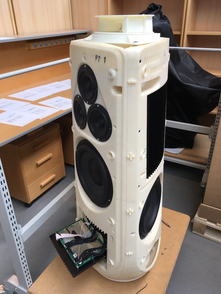
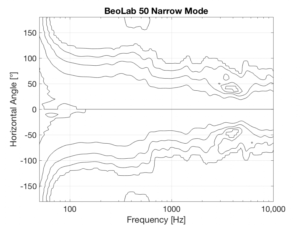
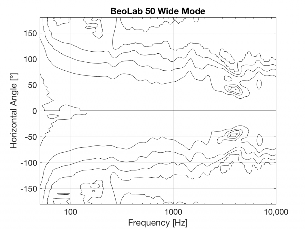
The three woofers and three midrange drivers of the BeoLab 50 (seen above in Figure 1) are each driven by its own amplifier, DAC and signal processing chain. This allows us to create a custom digital filter for each driver that allows us to control not only its magnitude response, but its behaviour both in time and phase (vs. frequency). This means that, just as in the BeoLab 90, the drivers can either cancel each other’s signals, or work together, in different directions radiating outwards from the loudspeaker. This means that, by manipulating the filters in the DSP (the Digital Signal Processing) chain, the loudspeaker can either produce a narrow or a wide beam of sound in the horizontal plane, according to the preferences of the listener.
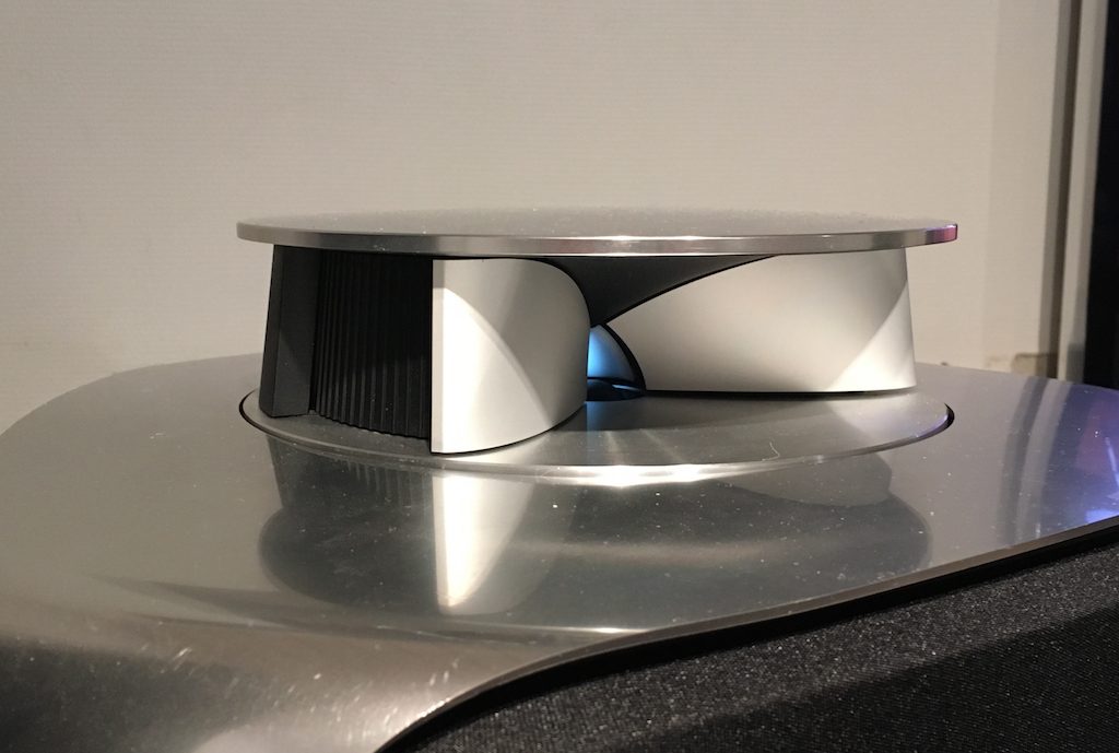
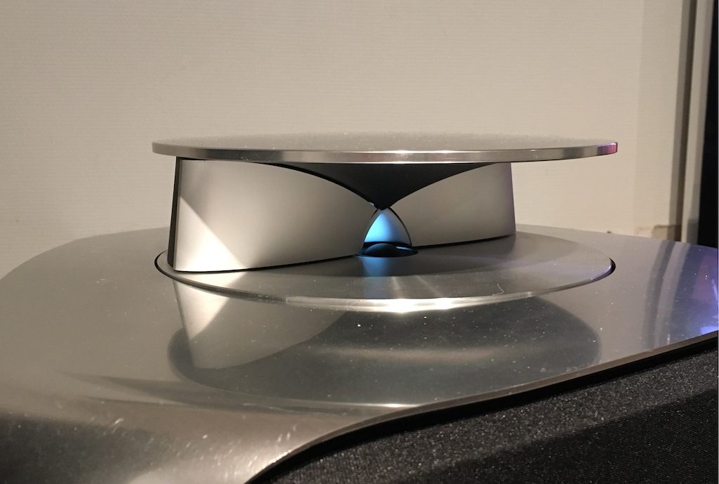
You’ll see that there is only one tweeter, and it is placed in an Acoustic Lens that is somewhat similar to the one that was first used in the BeoLab 5 in 2002. However, BeoLab 50’s Acoustic Lens is considerably different in a couple of respects.
Firstly, the geometry of the Lens has been completely re-engineered, resulting in a significant improvement in its behaviour over the frequency range of the loudspeaker driver. One of the obvious results of this change is its diameter – it’s much larger than the lens on the tweeter of the BeoLab 5. In addition, if you were to slice the BeoLab 50 Lens vertically, you will see that the shape of the curve has changed as well.
However, the Acoustic Lens was originally designed to ensure that the horizontal width of sound radiating from a tweeter was not only more like itself over a wider frequency range – but that it was also quite wide when compared to a conventional tweeter. So what’s an Acoustic Lens doing on a loudspeaker that can also be used in a Narrow mode? Well, another update to the Acoustic Lens is the movable “cheeks” on either side of the tweeter. These can be angled to a more narrow position that focuses the beam width of the tweeter to match the width of the midrange drivers.
In Wide Mode, the sides of the lens open up to produce a wider radiation pattern, just as in the original Acoustic Lens.
So, the BeoLab 50 provides a selectable Beam Width, but does so not only “merely” by changing filters in the DSP, but also with moving mechanical components.
Of course, changing the geometry of the Lens not only alters the directivity, but it changes the magnitude response of the tweeter as well – even in a free field (a theoretical, infinitely large room that is free of reflections). As a result, it was necessary to have a different tuning of the signal sent to the tweeter in order to compensate for that difference and ensure that the overall “sound” of the BeoLab 50 does not change when switching between the two beam widths. This is similar to what is done in the Active Room Compensation, where a different filter is required to compensate for the room’s acoustical behaviour for each beam width. This is because, at least as far as the room is concerned, changing the beam width changes how the loudspeaker couples to the room at different frequencies.
Guy says:
A good looking loudspeaker and wish you and B&O all the success in selling thousands of them.
Me? I’m going to keep and cherish my BL90s :)
Nicolas Dunn says:
Thank you very much for this breakdown Geoff! I am so happy to see these released
Preben Sørensen says:
Hi Geoff
I am happy to see that beam width control in the full frequency range including narrow mode has been implemented in BL50, as I was so impressed by the image location in BL90.
My dealer will be contacted right away.
Very B&O like to develop a mechanical solution for implementing tweeter narrow and wide modes.
Studying your earlier postings (I believe) I understand that the 3 woofers are necessary to achieve width control in the low frequencies.
However, I wander why it is not necessary having the 3 midrange speakers in different directions to be able to change the width between narrow and wide.
Can you elaborate on that?
Brg Preben (ps57)
geoff says:
Hi Preben,
As you probably know, the directivity of a single driver in a baffle changes with frequency throughout its bandwidth. If we consider the midranges alone, then we can say that, for each driver, the higher the frequency, the narrower its directivity. This means that, if we want to make the entire loudspeaker’s directivity as narrow as it is for the centre midrange at its highest frequency, then we need to use the two other midranges to cancel signals at lower frequencies.
However, if we want to make the loudspeaker’s directivity wider, then we can use the natural width of the centre midrange in its low frequency band, and then add width in its high frequency band by adding to it with the other two drivers (which also have naturally narrow beams at their high frequencies).
Of course, I’m over-simplifying considerably here. The truth is that we define a target directivity for the entire system, with tolerance limits over a given frequency band. Our development software then uses (1) those targets and (2) the directivity measurements of the drivers in the baffle, and outputs individualised FIR filters that generate the combined directivity we are looking for. This then has to be optimised using human intervention in an iterative process – create filters, listen to the result, correct for problems, and then repeat the process…
Hope this helps.
Cheers
– geoff
Preben Sørensen says:
Thanks for your explanation, Geoff.
By the way, a 2 way speaker (with 3 woofers and 1 acoustic lens creating beam width control) would be an interesting replacement of the discontinued BL3/BL11 set-up (and of course you cannot comment on that).
Brg Preben (ps57)
Preben Sørensen says:
There is a dip or peak at 4 kHz. Is that caused by the acoustic lens?
Your intuitive directivity plots in your B&O blog #48 is a better way in showing the frequency performance, as I see it. Would it be possible for you to show plot where you compare BL90/50/5?
Brg Preben (ps57)
geoff says:
Hi Preben,
It’s a narrow dip (narrow in frequency and narrow in space) around 4 kHz, about 45º off-axis. This is caused by interference between the tweeter and the midrange array which are time-aligned (and therefore phase-aligned) for the on-axis direction. As you come around to the side of the loudspeaker, the relative distances of the drivers change, resulting in a cancellation there.
There are a number of reasons why this is not a concern. The first is the narrowness of the affected frequency band. The second is not only the narrowness of the horizontal angle of the dip, but the angle of its centre. Lastly, and possibly most importantly, it should be remembered that this plot only shows one distance (3 m) and height. Of course, this plot would look very different at different distances (particularly if we go less than 3 m) and vertical angles (the integration of which determines the three-dimensional power response of the loudspeaker).
I’ll try to dig out my old Matlab code and do a future blog posting with different directivity plots… Someday… :-)
Cheers
-geoff
Simon-Haemmerle@web.de says:
Hallo Geoff,
first of all: great blog! I want to thank you for the very interesting insights.
Reading the Beolab 50s Technical Sound Guide, I noticed that you are using drivers from Tymphany in the Beolab 50 instead of drivers from Scan-Speak like in the Beolab 90. Is there a specific reason for that? Are the Tymphany drivers inferior to (or possibly even better than) the Scan-Speak drivers in any way?
Thank you!
Kind regards
Simon
geoff says:
Hi Simon,
Of course when we (or anyone else…) select the drivers for a given loudspeaker, there are many, many parameters that are weighed in the decision.
If we only talk about electroacoustic parameters, then the only honest way to answer your question is to say that the drivers in BeoLab 90 and the drivers in BeoLab 50 are (of course…) different from each other. Different linear responses, different Bl curves, different directivities, different sensitivities, different power handling, and so on and so on… In the end, the real-world implications of this (for us on the development team) are that the signal processing that we design for the tuning of the linear response, the directivity, and the non-linear behaviour are therefore also different. This is due to the fact that this processing must be customised to the hardware.
I recently took a course in baking French bread. One of the things that we learned there was that the amount of water you add to the flour is dependent on the relative humidity. The higher the ambient humidity of the air in the room, the more water is already in the flour, so the less water you need to add to make your bread. You have to adjust the recipe according to the conditions of the ingredients.
Similarly, the “recipe” in our loudspeakers is to combine all the “ingredients” (both hardware and software) correctly. If we change one ingredient (say, from one midrange driver to a different one – a different brand, a different model from the same manufacturer) then we have to adjust another ingredient (for example, the signal processing) accordingly…
However, if we’re going to get a little geeky about it, we could even say that two drivers of the same model from the same production line are also different from each other. This is the reason why, for the BeoLab 50 and 90, we have to measure each driver individually on the production line, and program customised filters into the loudspeaker to compensate for those differences.
We could even get more geeky and talk about how a single driver changes its own characteristics when it gets hot (which it does when you’re playing music…) which is why we have Thermal Compression Compensation on our high-end loudspeakers to counter-act that behaviour…
Cheers
-geoff
Simon says:
Hi Goeff,
Thank you for your answer! It’s downright impressive how much work goes in every individual B&O speaker.
Does the Beolab 50 also feature the Thermal Compression Compensation?
Greetings,
Simon
geoff says:
Hi Simon
Yes.
Cheers
-geoff