In Part 1, I talked about how any measurement of an audio device tells you something about how it behaves, but you need to know a LOT more than what you can learn from one measurements. This is especially true for a loudspeaker where you have the extra dimensions of physical space to consider.
Thought experiment: Fridges vs. Mosquitos
Consider a situation where you’re sitting at your kitchen table, and you can hear the compressor in your fridge humming/buzzing over on the other side of the room. If you make a small movement in your chair, the hum from the fridge sounds the same to you. This is partly because the distance from the fridge to you is much bigger than the changes in that distance that result from you shifting your butt.
Now think about the times you’ve been trying to sleep on a summer night, and there’s a mosquito that is flying near your ear. Very small changes in the location of that mosquito result in VERY big changes in how it sounds to you. This is because, relative to the distance to the mosquito, the changes in distance are big.
In other words, in the case of the fridge (that’s say, 3 m away) by moving 10 cm in your chair, you were changing the distance by about 3%, but the mosquito was changing its distance by more than 100% by moving just from 1 cm to 2 cm away.
In other words, a small change in distance makes a big change in sound when the distance is small to begin with.
The challenges of measuring headphones
The methods we use for measuring the magnitude response of a pair of headphones is similar to that used for measuring a loudspeaker. We send a measurement signal to the headphones from a computer, that signal comes out and is received by a microphone that sends its output back to the computer. The computer then is used to determine the difference between what it sent out and what came back. Simple, right?
Wrong.
The problems start with the fact that there are some fundamental differences between headphones and loudspeakers. For starters, there’s no “listening room” with headphones, so we don’t put a microphone 3 m away from the headphones: that wouldn’t make any sense. Instead, we put the headphones on some kind of a device that either simulates an ear, or a head, or a head with ears (with or without ear canals), and that device has a microphone (roughly) where your eardrum would be. Simple, right?
Wrong.
The problem in that sentence was the word “simulates”. How do you simulate an ear or a head or a head with ears? My ears are not shaped identically to yours or anyone else’s. My head is a different size than yours. I don’t have any hair, but you might. I wear glasses, but you might not. There are many things that make us different physically, so how can the device that we use to measure the headphones “simulate” us all? The simple answer to this question is “it can’t.”
This problem is compounded with the fact that measurement devices are usually made out of plastic and metal instead of human skin, so the headphones themselves “see” a different “acoustic load” on the measurement device than they do when they’re on a human head. (The people I work with call this your acoustic impedance.)
However, if your day job is to develop or test headphones, you need to use something to measure how they’re behaving. So, we do.
Headphone measurement systems
There are three basic types of devices that are used to measure headphones.
- an artificial ear is typically a metal plate with a depression in the middle. At the bottom of the depression is a microphone. In theory, the acoustic impedance of this is similar to a human ear/pinna + the surrounding part of your head. In practice, this is impossible.
- a headphone test fixture looks like a big metal can lying on its side (about the size of an old coffee can, for example) on a base. It might have flat metal sides, or it could have rubber pinnae (the fancy word for ears) mounted on it instead. In the centre of each circular end is a microphone.
- a dummy head looks like a simplified model of a human head (typically a man’s head). It might have pinnae, but it might not. If it does, those pinnae might look very much like human ears, or they could look like simplified versions instead. There are microphones where you would expect them, and they might be at the bottom of ear canals, but you can also get dummy heads without ear canals where the microphones are flush with the side of the head.
The test system you use is up to you – but you have to know that they will all tell you something different. This is not only because each of them has a different acoustic response, but also because their different shapes and materials make the headphones themselves behave differently.
That last sentence is important to remember, not just for headphone measurement systems but also for you. If your head and my head are different from each other, AND your pinnae and my pinnae are different from each other, THEN, if I lend you my headphones, the headphones themselves will behave differently on your head than they do on my head. It’s not just our opinions of how they sound that are different – they actually sound different at our two sets of eardrums.
General headphone types
If I oversimplify headphone design, we can talk about two basic acoustical type of headphones: They can be closed (where the back of the diaphragm is enclosed in a sealed cabinet, and so the outside of the headphones is typically made of metal or plastic) or open (where the back of the diaphragm is exposed to the outside world, typically through a metal screen). I’d say that some kinds of headphones can be called semi-open, which just means that the screen has smaller (and/or fewer) holes in it, so there’s less acoustical “transparency” to the outside world.
Examples
To show that all these combinations are different, I took three pairs of headphones
- open headphones
- semi-open headphones
- closed headphones
and I measured each of them on three test devices
- artificial “simplified” ear
- text fixture with a flat-plate
- dummy head
In addition, to illustrate an additional issue (the “mosquito problem”), I did each of these 9 measurements 5 times, removing and replacing the headphones between each measurement. I was intentionally sloppy when placing the headphones on the devices, but kept my accuracy within ±5 mm of the “correct” location. I also changed the clamping force of the headphones on the test devices (by changing the extension of the headband to a random place each time) since this also has a measurable effect on the measured response.
Do not bother asking which headphones I measured or which test systems I used. I’m not telling, since it doesn’t matter. Not to me, anyway…
The raw results
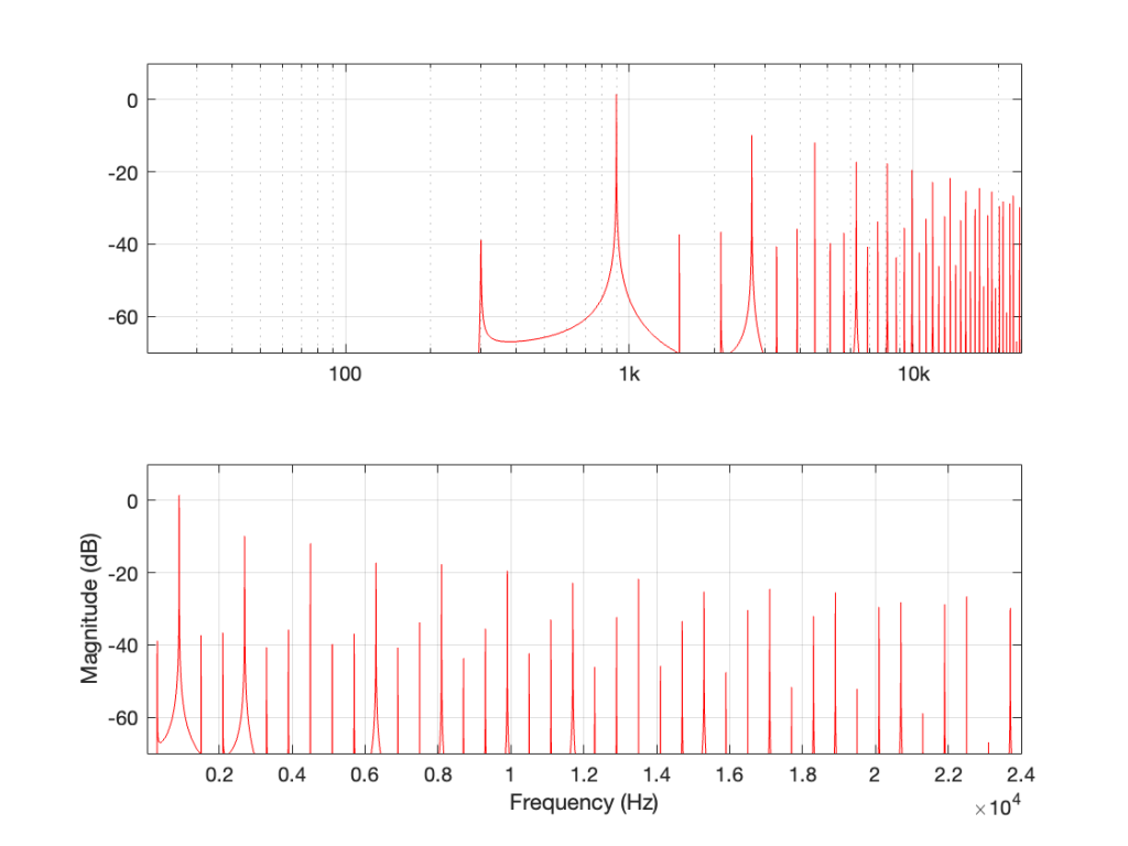
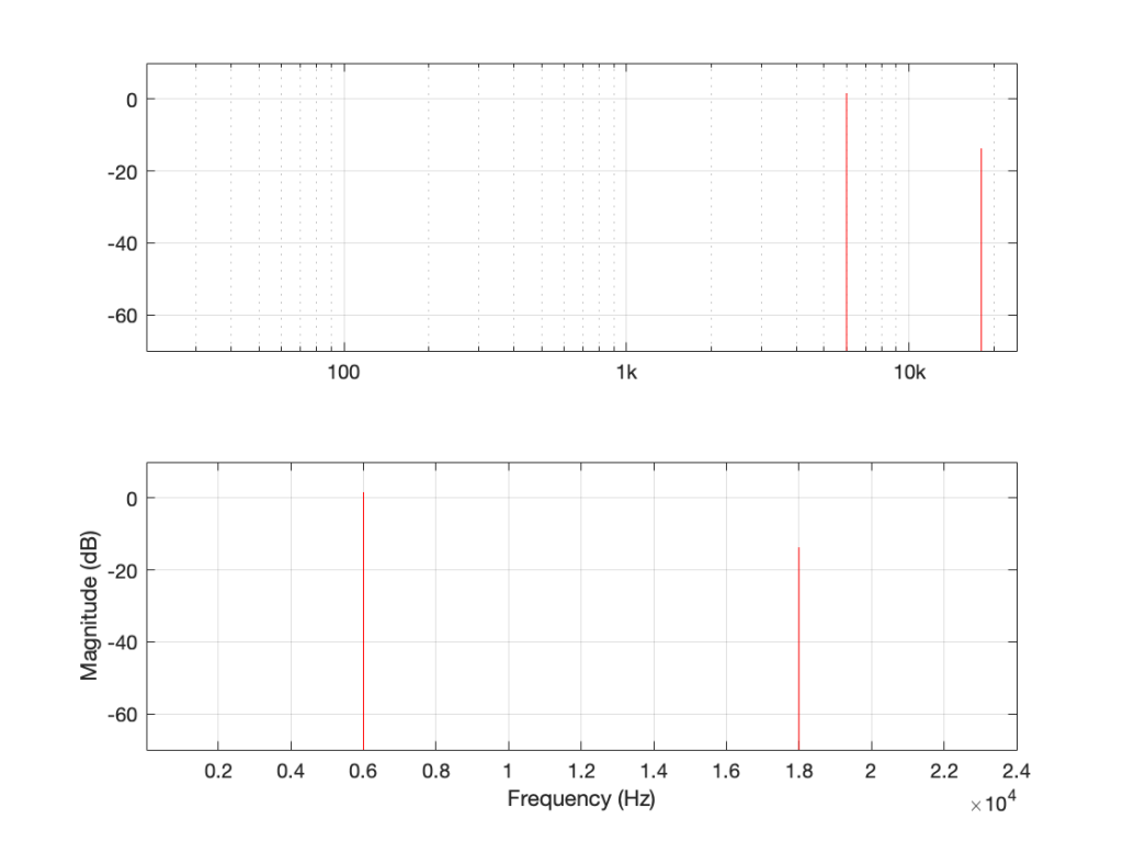
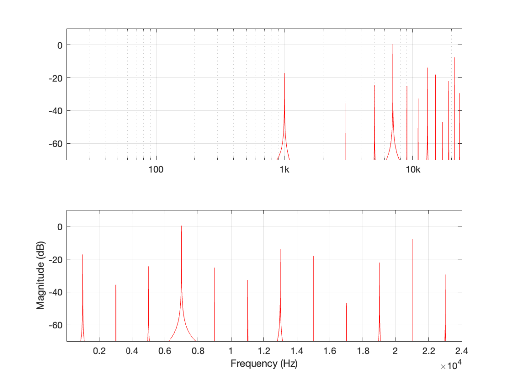
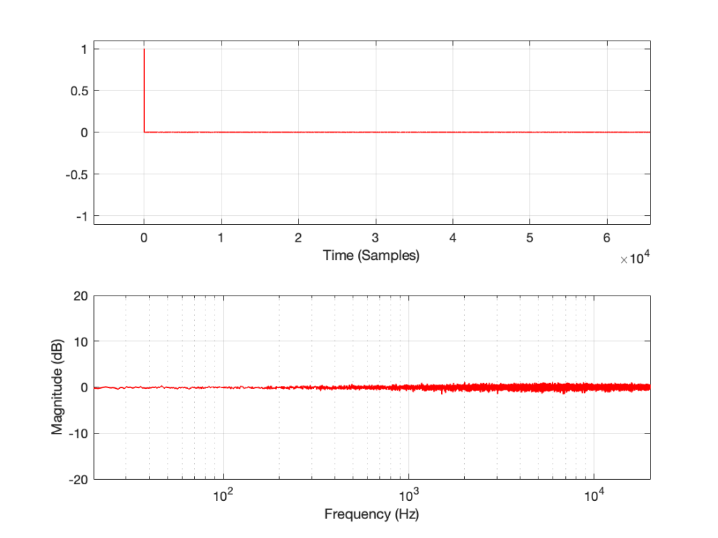
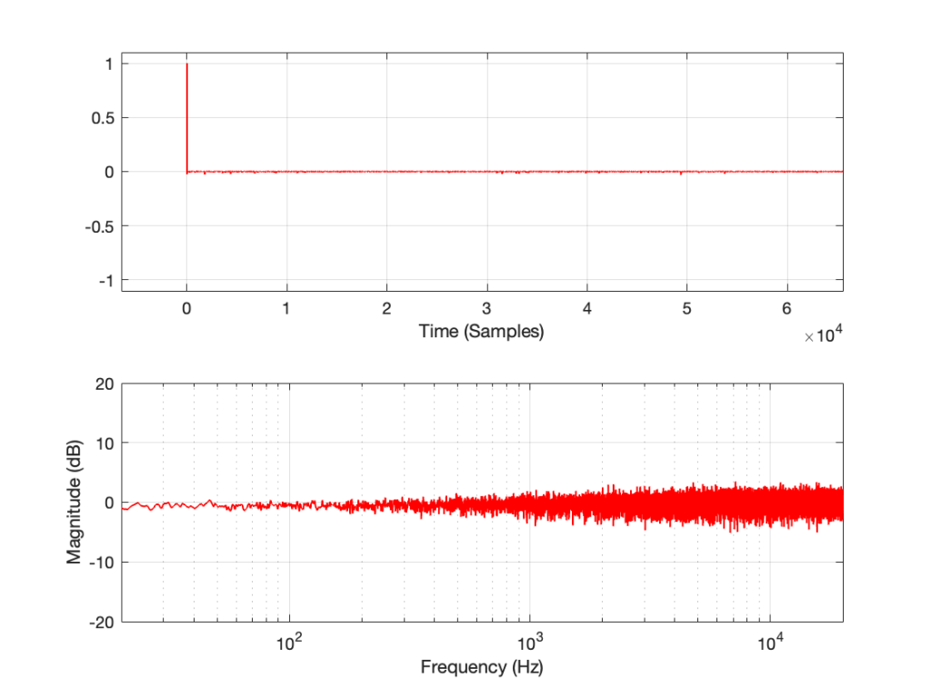
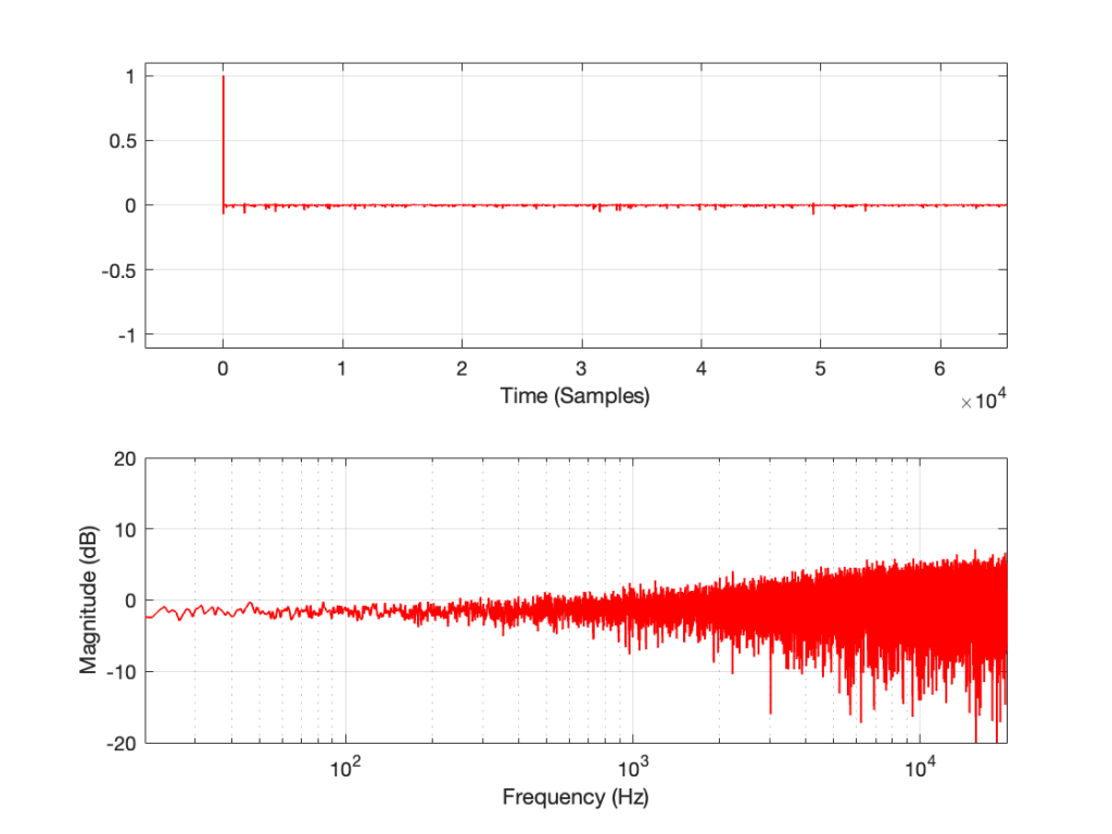
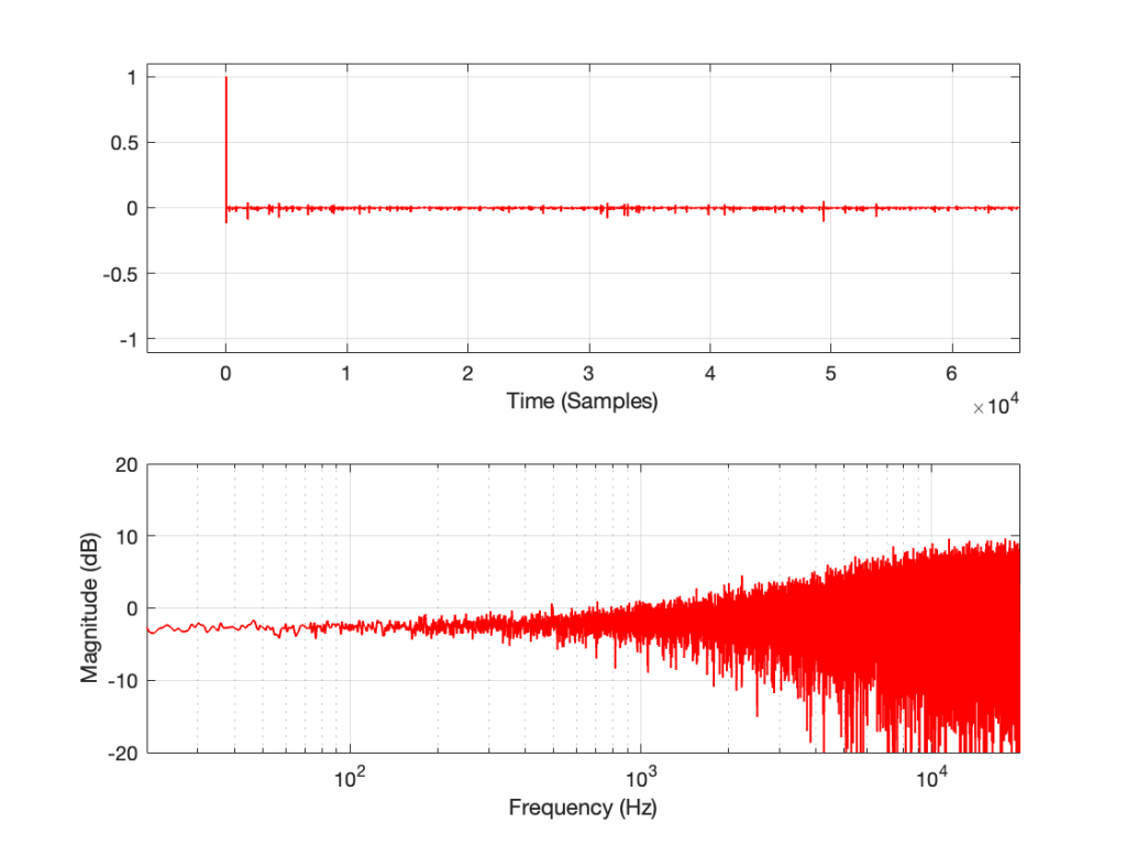
I did these measurements using a 10-second sinusoidal sweep from 2 Hz to Nyquist, on a system running at 96 kHz. I’m plotting the magnitude responses with a range from 10 Hz to 40 kHz. However, since the sweep starts at 2 Hz, you can’t really trust the results below 20 Hz (a decade below the lowest frequency of interest is a good rule of thumb when using sine sweeps).
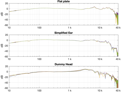
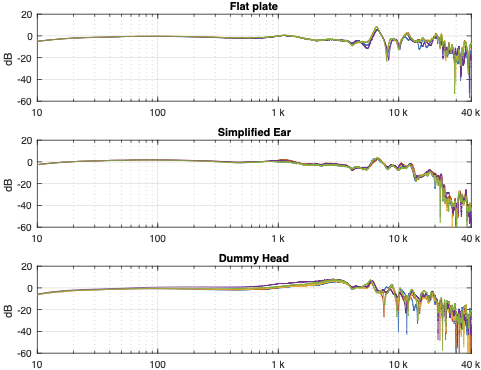
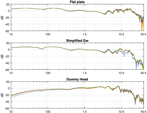
Looking at the results in the plots above, you can come to some very quick conclusions:
- All of the measurements are different from each other, even when you’re looking at the same headphones on the same measurement device. This is especially true in the high frequency bands.
- Each pair of headphones looks like it has a different response on each measurement system.
For example, looking at Figure 3, the response of the headphones looks different when measured on a flat plate than on a dummy head. - The difference in the results of the systems are different with the different headphone types.
For example, the three sets of plots for the “semi-open” headphones (Fig. 2) look more similar to each other than the three sets of plots for the “closed” headphones (Fig. 3) - the scale of these differences is big. Notice that we have an 80 dB scale on all plots… We’re not dealing with subtleties here…
In Part 3 of this series, we’ll dig into those raw results a little to compare and contrast them and talk a little about why they are as different as they are.