
Category: audio
Objective Audiophilia
This blog seems to be pretty good. I was just made aware of it by a friend on the weekend.
Social Media vs. Music
Finally, I’ve found someone who shares my frustration with the Interweb’s determination to use my personal preferences as advertising material…
B&O Tech: Video Engine Customisation Part 1: Bass Management
#33 in a series of articles about the technology behind Bang & Olufsen loudspeakers
Earlier today (just after lunch), I had a colleague drop by to ask some technical questions about his new BeoVision 11. He’s done the setup with his external loudspeakers, but wanted to know if (mostly “how”…) he could customise his bass management settings to optimise his system. So, we went into the listening room to walk through the process. Since he was discussing this with some other colleagues around the lunch table, it turned out that we discovered that he wasn’t the only one who wanted to learn this stuff – so we wound up with a little group of 8 or 10 asking lots of questions that usually started with “but what if I wanted to…” After a half an hour or so, we all realised that this information should be shared with more people – so here I am, sharing.
This article is going to dive into the audio technical capabilities of what we call the “Video Engine” (the processing hardware inside the BeoPlay V1, the BeoVision 11, BeoVision Avant, and BeoSystem 4). For all of these devices, the software and its capabilities with respect to processing of audio signals are identical. Of course, the hardware capabilities are different – for example, the number of output channels are different from product to product – but everything I’m describing below can be done on all of those products.
One other warning: Almost of the menus that I direct you to in the text below are accessed as follows:
“MENU” button on remote control -> Setup -> Sound -> Speaker Group -> NAME -> Advanced Settings -> Bass Management
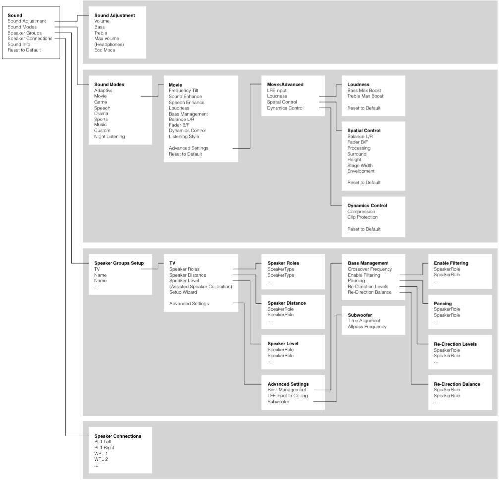
You can see this in the menu map, below.
So, let’s start by looking at a signal flow block diagram of the way the audio is processed inside the bass management processing.
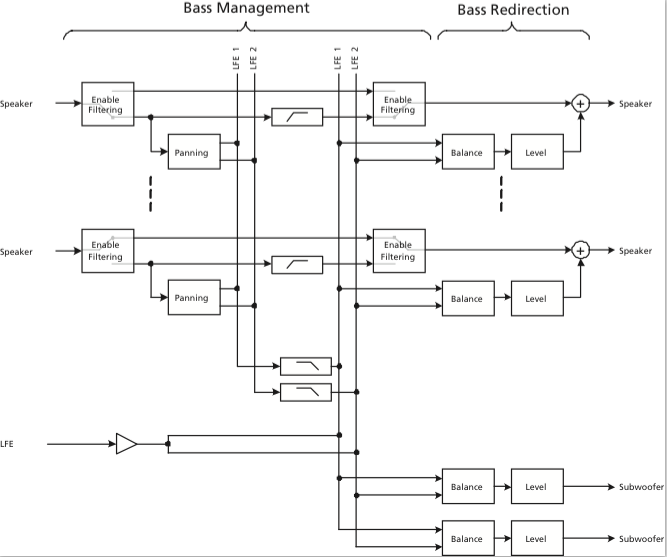
So, let’s start at the input to the system:
The “Speaker” signals coming in on the left are coming from the 16 output channels of the True Image upmixer (if you’re using it) or they are the direct 2.0, 5.1, or 7.1 (or other formats, if you’re weird like me) channels from the source. (We’ll ignore the LFE input for now – but we’ll come back to it later…)
The first thing the signals encounter is the switch labelled Enable Filtering (which is also the name of the menu item where you control this parameter). This where you decide whether you want the bass removed from the signal or not. For smaller loudspeakers (assuming that you have a big some in the same system) you will want to Enable the Filtering and remove the bass to re-direct it to the larger loudspeaker. If you have larger loudspeakers in the same system, you may not want to re-direct the signals. So, let’s say that you have BeoLab 20’s as the Left Front and Right Front (Lf / Rf for the rest of this article), BeoLab 17’s as the Left Surround and Right Surround (Ls / Rs), and the internal loudspeakers as the Centre Front (Cf), you will want to Enable Filtering on the Ls, Rs, and Cf signals. This will remove the bass from those channels and re-direct it somewhere else (to the 20’s – but we make that decision downstream…). You will not want to Enable Filtering for the 20’s since you’ll be using them as the “subwoofers”.
Assuming that you’ve enabled the filtering, then the signal takes the lower path and splits to go in two directions. The upper direction is to a high-pass filter. This is a 4th order highpass that is 6.02 dB down at the frequency chosen in the Crossover Frequency menu. We use a 4th order filter because the crossover in our bass management system is a 4th order Linkwitz-Riley design. As you can see in the block diagram, the output of the highs filter is routed directly to the output to the loudspeaker. The low path in the split goes to a block called Panning. This is where you decide, on a channel-by-channel basis, whether the signal should be routed to the left or the right bass channel (or some mix of the two). For example, if you have a Ls loudspeaker that you’re bass managing, you will probably want to direct its bass to the Left bass channel. The Rs loudspeaker’s bass will probably direct to the Right bass channel, and the Cf loudspeaker’s bass will go to both. (Of course, if, at the end of all this, you only have one subwoofer, then it doesn’t matter, since the Left and Right bass channels will be summed anyway.) The outputs of all the panning blocks are added together to form the two bass channels – although, you may notice in the block diagram, they are still full-range signals at this point (internally) in the signal flow, since we haven’t low-pass filtered them yet.
Next, the “outputs” of the two bass channels are low-pass filtered using a 4th order filter on each. Again, this is due to the 4th order Linkwitz-Riley crossover design. The cutoff frequency of these two low pass filters are identical to the highpass filters which are all identical to each other. There is a very good reason for this. Whenever you apply a minimum-phase filter (which ours are, in this case) of any kind to an audio signal, you get two results: one is a change in the magnitude response of the signal, the other is a change in its phase response. One of the “beautiful” aspects of the Linkwitz-Riley crossover design is that the Low Pass and High Pass filters are 360° out-of-phase with each other at all frequencies. This is (sort of…) the same as being in-phase at all frequencies – so the signals add back together nicely. If, however, you use a different cutoff frequency for the low and high pass components, then the phase responses don’t line up nicely – and things don’t add back together equally at all frequencies. If you have audio channels that have the same signals (say, for example, the bass guitar in both the Lf and Rf at the same time – completely correlated) then this also means that you’ll have to use the same filter characteristics on both of those channels. So, the moral of the story here is that, in a bass management system, there can be only one crossover frequency to rule them all.
You may be wondering why we add the signals before we apply the low-pass filter. The only reason for this was an optimisation of the computing power – whether we apply the filter on each input channel (remember, there are up to 16 of those…) or on two summed outputs, the result is the same. So, it’s smarter from a DSP MIPS-load point of view to use two filters instead of 16 if the result is identical (all of our processing is in floating point, so there’s no worry of overloading the system internally).
Now comes the point where we take the low-frequency components of the bass-managed signals and add them to the incoming LFE channel. You may notice a little triangle on that LFE channel before it gets summed. This is not the +10 dB that is normally added to the LFE channel – that has already happened before it arrived at the bass management system. This gain is a reduction, since we’re splitting the signal to two internal bass channels that may get added back together (if you have only one subwoofer, for example). If we didn’t drop the gain here, you’d wind up with too much LFE in the summed output later.
Now we have the combined LFE and bass management low-frequencies on two (left and right) bass channels, ready to go somewhere – but the question is “where?” We have two decisions left to make. The first is the Re-direction Balance. This is basically the same as a good-old-fashioned “balance” control on your parents’ stereo system. Here you can decide (for a given loudspeaker output) whether it gets the Left bass channel, the Right bass channel, or a combination of the two (you only have three options here). If you have a single subwoofer, you’ll probably be smart to take the “combination” option. If you have separate Left and Right subwoofers, then you’ll want to direct the Left bass channel to the left subwoofer and the right to the right.
Finally, you get to the Bass Re-direction Level menu. This is where you decide the gain that should be applied to the bass channel that is sent to the particular loudspeaker. If you have one subwoofer and you want to send it everything, then its Redirection level will by 0 dB and the other loudspeakers will be -100 dB. If you want to send bass everywhere, then set everything to 0 dB (this is not necessarily a good idea – unless you REALLY like bass…).
It’s important to note that ANY loudspeaker connected in your system can be treated like a “subwoofer” – which does not necessarily mean that it has a “subwoofer” Speaker Role. For example, in my system, I use my Lf and Rf loudspeakers as the Lf and Rf channels in addition to the subwoofers. This can be seen in the menus as the Lf and Rf Re-direction levels set to 0 dB (and all others are set to -100 dB to keep the bass out of the smaller loudspeakers).
Special Treatment for Subwoofers
As you can see in the block diagram, there are two “subwoofer” outputs which, as far as the bass management is concerned, are identical to other loudspeakers. However, the Subwoofer outputs have two additional controls downstream for customising the alignment with the rest of the system. The first is a Time Alignment adjustment which can be set from -30 ms to +30 ms. If this value is positive, then the subwoofer output is delayed relative to the rest of the system. If it’s negative, then the rest of the system is delayed relative to the subwoofer. There are lots of reasons why you might want to do either of these on top of your Speaker Distance adjustment – but I’m not going to get into that here.
The second control is a first-order Allpass filter. This will be 90° out of phase at the frequency specified on the screen – going to 180° out at a maximum in the high frequencies. The reason to use this would be to align for phase response differences between your subwoofer’s high end and your main “main loudspeakers'” low-end. Say, for example, you have a closed-box subwoofer, but ported (or slave driver-based) main loudspeakers. You may need some phase correction in a case like this to clean up the addition of the signals across the crossover region. Of course, if you have different main loudspeakers, then one allpass filter on your subwoofer can’t correct for all of the different responses in one shot. Of course, if you don’t want to have an allpass filter in your subwoofer signal path, you can bypass it.
For more information about the stuff I talked about here (including cool things like phase response plots of the allpass filter), check out the Technical Sound Guide for the Video Engine-based products. This is downloadable from this page for example.
B&O Tech: The Naked Truth V
#32 in a series of articles about the technology behind Bang & Olufsen loudspeakers
This posting: something new, something old…
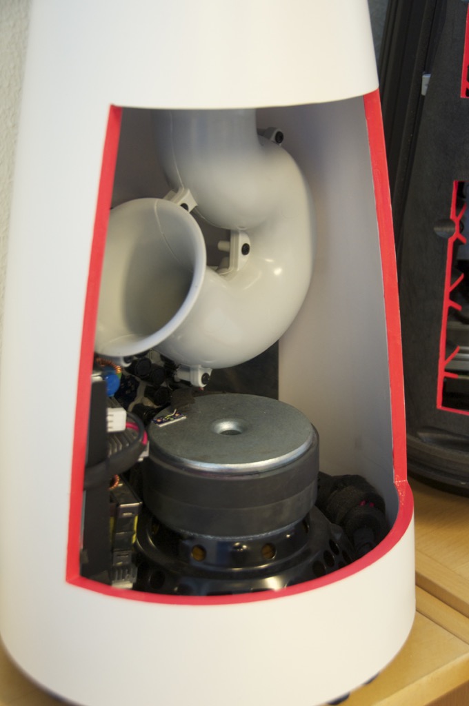
First, the insides of the BeoLab 14 subwoofer. The obvious part is the port curling around to get the right length in a somewhat shorter package. This concept has been around for a while as you can see when you look at a trumpet or a tuba…
The silver-coloured disc right below the bottom of the port is the pole piece of the woofer. The black ring around this is the ferrite magnet. In the background you can see the circuit boards containing the power supply, DSP and amplifiers for the sub and the satellites. For a better view of this, check out this page.
The reasons the end of the port is flared like a trumpet bell is to reduce the velocity of the air at the end of the pipe. This reduces turbulence which, in turn, means that there is less noise or “port chuffing” at the resonant frequency of the port. Of course, the other end of the port at the top of the subwoofer is also flared for the same reason.
As I mentioned in a previous posting, the DSP is constantly calculating the air velocity inside the port and doesn’t allow it to exceed a value that we determined in the tuning. This doesn’t mean that it’s impossible to hear the turbulence – if you test the system with a sine tone, you’ll hear it – but that was a tuning decision we made. This is because we pushed the output to a point that is almost always inaudible with music – but can be heard with sine tones. If we hadn’t done that, the cost would have been a subwoofer with less bass output.


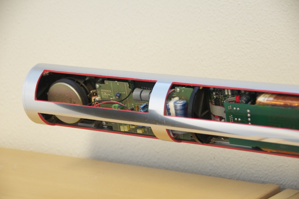
Now for something a little older… This is a BeoLab 3500 (we’re not looking at the BeoLab 7-4 on the shelf below)
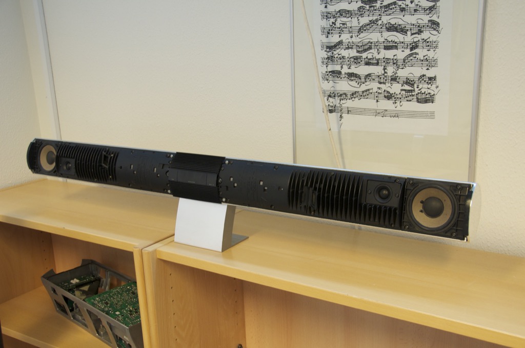
Below is a close-up of the tweeter and woofer. You may notice that you can see light through the edge of the surround of the woofer. This is because we cut it with a knife for a different demonstration – it’s not normal… You can also see the fins which help to keep the electronics cool.


As you can see in the photos below, all the electronics are inside the woofer enclosures. The tweeter has its own built-in chamber, so it’s sealed from the woofer enclosure.


This looks interesting…
For those of you who are interested in knowing a little more about what’s in a recording…

Weekend project
Record label discovery of the week
After 12 years in Denmark and I finally stumbled upon this – due to a review in Gramophone magazine…

I placed an order for the multichannel SACD of Rued Langgard’s String Quartets (vol 2) by the Nightingale String Quartet. Looking forward to hearing it!
Re-thinking perception

Jingle Jerk?
