#37 in a series of articles about the technology behind Bang & Olufsen loudspeakers
In the last posting, I described a little experiment that we did where we could easily be accused of asking a stupid question and getting an obvious answer. This posting is a little different, although I’ll also describe a little experiment where we asked a much-less-stupid question and got an answer we weren’t looking for… However, before I describe the experiment itself, we’ll have to start with a little background information.
Let’s say that we wanted to build a “simple” two-way loudspeaker with a tweeter and a woofer in a box like the one shown in Figure 1.
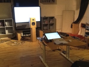
Since we’re Bang & Olufsen, it is implied that this will be a fully active, DSP-based loudspeaker. Let’s also, for the sake of simplicity, say that we used loudspeaker drivers and other components with absolutely no linear distortion artefacts (I can dream, can’t I?). This means that we can apply any kind of filter we like to each of the two loudspeaker drivers to result in whatever response we want (in a given direction in a “free field” (a space with no reflecting surfaces, extending to infinity in all directions) – for more information on this, please read this posting and/or this posting).
Now, it’s fairly reasonable to assume that one portion of a good starting point for a loudspeaker’s acoustic response is to have a flat magnitude response when measured on-axis in a free field. This means that, if you have the loudspeaker in a space that has no reflections, and you are directly in front of it, no frequency will be louder than any other (within some limits, of course…). In fact, this is the way a lot of studio monitor loudspeakers are tuned (which makes sense, since many studio control rooms don’t have a lot of reflections as was discussed here).
The problem is that, if you do make a loudspeaker that is flat-on-axis, you’ll probably have problems in its power response (for a description of what a loudspeaker’s “power response” is, see here). This is dependent on a lot of things like the crossover frequency, the sizes and shapes of the drivers, the phase responses of the crossover filters, the shape of the cabinet, and other things. However, if we were to simplify, we could say that a two-way loudspeaker (say, with a 4th order Linkwitz-Riley crossover, just to pick one type…) that is flat on-axis, will have a dip in its power response at the crossover frequency. This is because, although the two drivers (the tweeter and the woofer) add together nicely in one location (on-axis, directly in front of the loudspeaker) they do not add together nicely anywhere else (because the distances to the two drivers from the listening position are probably not matched, particularly when you go vertical…).
So, one basic problem with building a “simple” two-way loudspeaker is that you have to choose to either have a flat magnitude response on-axis, or a smooth power response (without a dip) – but you can’t have both. (If you want to really dig into this, I’d recommend starting with J. Vanderkooy & S.P. Lipshitz, “Power Response of Loudspeakers with Noncoincident Drivers — The Influence of Crossover Design,” J. Audio Eng. Soc., Vol. 34, No. 4, pp. 236-244 (Apr. 1986).)
This basic problem raised a question in the head of one of our acoustical engineers, Gert Munch. He started to wonder how we could build a loudspeaker that could have a flat magnitude response on-axis and still have a smooth power response that didn’t suffer from a dip at the crossover. One possible solution is to build a loudspeaker with the desired on-axis response, and then somehow create an additional portion of the loudspeaker that could “fill up” the dip in the power response by sending energy into the room without it affecting the on-axis response.
One possible way to do this is to use an extra loudspeaker with a “dipole” characteristic – a two-sided loudspeaker where the same signal is sent to both sides, but in opposite polarity. This means that, when one side of the loudspeaker produces a high pressure, the other side produces a low. When you sit on one side of the loudspeaker or the other, then you hear a signal. However, if you sit “on edge” to the loudspeaker, you hear nothing, since the two sides of the loudspeaker cancel each other out (in theory).
So, Gert’s idea was to add a two-way dipole loudspeaker on the top of a normal two-way loudspeaker and to just use the dipole (which became known as a “shark fin” – shown in Figure 2) to add energy around the crossover frequency of the “normal” loudspeaker. Since the edge of the dipole was facing forwards, the theory was that none of its sound would have an effect on the on-axis response of the two-way loudspeaker below it.
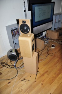
So, the question to answer was:
“Which sounds better:
- a loudspeaker tuned to be flat on-axis, but with no correction for its power response
- a loudspeaker that was tuned to have a smooth power response (in other words, with a “bump” around the crossover)
- a loudspeaker that was tuned to be flat on-axis and had a power response correction provided by the dipole
?”
Since each of the 6 loudspeaker drivers in our model loudspeaker was independently controllable, this was an easy comparison to do on-the-fly, so we tried it out.
Also, just to be certain, we tried two different orientations of the dipole, both of which had the “null” – the edge of the loudspeaker – facing the listening position. The first orientation is shown in Figures 2 and 3. The second orientation is shown in Figure 4.
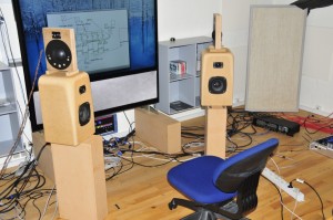
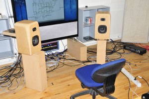
So, a bunch of us sat in the listening room for a week or so, listening to the various possible tunings of the loudspeakers, in various positions in the room, with various types of music. We each had an opinion about the whether we liked one configuration more or less than another. However, one thing that was noticeable was that there was an effect not only on the timbral impression of the loudspeakers (the tone colour) – but also on the spatial presentation of the pair. As we switched between the different tunings, phantom images changed in width and distance, and envelopment (when it existed in the recording) also changed.
This was particularly noticeable when the loudspeakers were closer to a reflecting surface, as is shown in Figure 5.
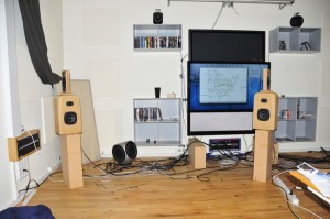
The end result was a bunch of different conclusions:
- The three different configurations of the loudspeaker (listed above) sounded different. (this was not a big surprise)
- A two-way loudspeaker tuned to have a smooth power response and a loudspeaker with a flat on-axis response with a shark fin smoothing the power response sounded different – but mostly spatially.
- Switching between those two loudspeaker configurations listed in Point #2 basically meant that we were switching between two different loudspeakers with the same power response, but different directivities (a fancy word meaning “directional behaviours”).
- The dipole loudspeaker’s output was audible at the listening position because of the sidewall reflections in the case where the dipole was on top.
- Switching the dipole on and off had a noticeable effect on the phantom image distance and width… When the dipole was turned on, the sidewall reflections were obviously louder, and the phantom images moved to a distance from the listening position roughly the same as the distance to the loudspeakers themselves. At the same time, the phantom image width increased and became “cloudy” or “fuzzy” and less precise.
All of those little conclusions could be folded into two big ones:
- The original idea of using a dipole to fill in the power response of the loudspeaker doesn’t work well enough in all situations because we don’t know where the reflective surfaces around the loudspeaker will be in any given configuration.
- Being able to control the directivity of the loudspeaker (specifically, how much energy is coming from the sidewall reflections) is a very interesting control parameter that we should look into…
So, this is where the concept of the shark fin died, but where the idea of “Beam Width Control” began.
Well… more accurately: it was the beginning of our thinking that being able to change the beam width (or the “directivity”, if you’re a geek) of the loudspeaker would be a useful “handle” in the hands of our customers. The idea that was born was something along the lines of the following: “If a customer could change the beam width of a loudspeaker, then (s)he could change it from being a narrow-directivity loudspeaker for people with one chair and no friends to a wide-directivity loudspeaker for people with a sofa and some friends to an omni-directivity loudspeaker for people throwing a party – all just by the flick of a switch…”
For more information on Beam Width Control:
Millemissen says:
Hi Geoff,
I guess we (= you) are talking about ‘a switch’ located in the ‘audio-engine’ in a BeoVision or a BeoSound – more than about ‘a switch’ located on the backside of a speaker?
‘A switch’ that could be ‘flicked’ via a remote ;-)
By the way – did you know that ‘Flick of the Switch’ is the title an AC/DC album —- Heavy stuff, ready for the ‘omni-directivity’ setting ;-))
geoff says:
Hi MM,
switches come in many guises. :-)
cheers,
-g