#7 in a series of articles about the technology behind Bang & Olufsen loudspeakers
My official job title at Bang & Olufsen is “Tonmeister and Technology Specialist in Sound Design”. The second half of that title is a bit weird – what is a “sound designer” and why would B&O want to have one on staff?
To answer that question, let’s start by talking about how a loudspeaker behaves in a real room. In many respects, a loudspeaker is like a lamp. Turn on a lamp and look at where the light goes. Some of it goes directly on what you want to look at – like the book you’re trying to read, for example. More of the light goes in other directions – it radiates outwards and reflects off of the walls, floor, ceiling, and furniture. And, if your lamp is anything like the one in my living room, then the light that shines directly on your book is not the most important part. In fact, if there was no direct light shining on the book, you would probably still be able to read your book because of the light reflecting towards your book off of everything else in the room.
A loudspeaker is basically the same thing – you have some sound that radiates directly out of the loudspeaker towards the listening position (assuming that the loudspeaker is “aimed” at the listening position) like a laser beam (like the light shining directly on your book – this is called the loudspeaker’s “on-axis magnitude response” or the “frequency response“). In addition to this, you have the sound that radiates outwards in all directions simultaneously like a big ball expanding in all three dimensions (this is called the “power response” of the loudspeaker). There are a couple of things to think about here. The first is that the sound that is coming directly from the loudspeaker to the listening position isn’t necessarily in the direction that the people who built the loudspeaker would call “on-axis” – in fact, more than likely, it’s slightly off-axis. This is okay, since you can think of a loudspeaker’s principal axis of radiation more like the beam from a flashlight than a laser beam (so you have a “listening window” instead of a single spot). The second thing to remember is that, in most listening situations, you are hearing FAR more energy from the loudspeaker’s total power response than you do from the direct sound’s magnitude response. In fact, in a lot of situations, you don’t have any direct sound at all – just power response filling up the room and reflected back to you. (If you’d like to learn more about this concept, read this posting to start off.)
The (rather important) moral of this short story is that the power response is at least as important as the magnitude response – and usually much more important. The problem is that, if you read loudspeaker reviews in magazines, you get the impression that the on-axis magnitude response is the most important thing there is to know about a loudspeaker. This is simply not true – the on-axis response of a loudspeaker is one of the easier things to measure, so that’s what gets measured by most people. It’s very difficult to do a reliable power response measurement, so most people don’t do one. Keep this in mind as you keep reading.
So, what are the steps we take when we tune our loudspeakers during the development process?
Step #1: Measurements
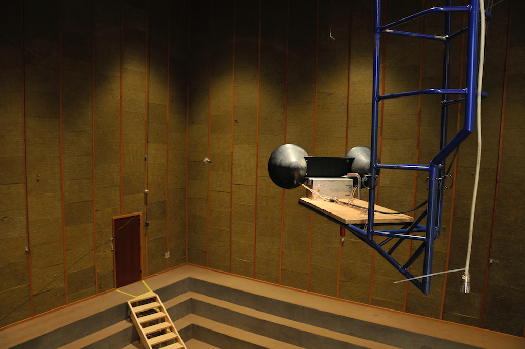
The prototype is put on the crane in the Cube and the linear part of its acoustic response is measured by the acoustical engineer assigned to the project. The output from these measurements consists of four final measurements:
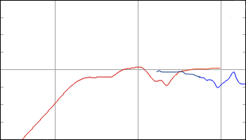
- the on-axis frequency response
- the frequency response of the loudspeaker at a lot of different angles in all directions (not just around the loudspeaker’s “equator” but also above and below it)
- a kind of an average response in a “listening window”
- the power response (made by adding the results of all the measurements done in all directions)
Since we make DSP-based active loudspeakers (unlike passive loudspeakers) the angular direction that is chosen as the “on-axis” location is arbitrary. This is because the final response from each loudspeaker driver and the delays that are used to time-align them are determined by the filtering that we apply in the DSP. I’ll talk about this in a future posting. However, what this means is that “on-axis” is “wherever we decide it to be” – NOT “directly in front of the tweeter” or “directly in front of the loudspeaker”. So, we do a measurement of the frequency response (which is comprised of the magnitude response and the phase response) of the loudspeaker in the absence of any wall reflections at some distance, on a line that has been determined to be the “on-axis” direction.

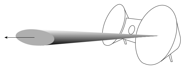
- An example of the “on-axis” direction. Note that this is not necessarily the actual on-axis direction for the BeoSound 8 – it’s merely an artist’s conception of the idea of “on-axis”.
The power response of a loudspeaker is kind-of-sort-of the sum of its magnitude responses in all directions. This is essentially a measure of the total acoustic energy that a loudspeaker sends into a room in all directions at the same time. So, instead of thinking of a loudspeaker as a laser beam (as in the on-axis response), this considers the loudspeaker as a naked light bulb, sending sound everywhere (which is actually a little closer to the truth).

- My attempt to represent the power response – a sphere of sound that radiates in all directions in 3D space from the loudspeaker.
The listening window is an area that has the on-axis line as its centre. It’s an oval-shaped area that is wider than it is high, that represents an area in front of the loudspeaker where we think that this listeners will typically be located.
- The “Listening Window”. Note that it’s wider than it is high, and that its centre is the “on-axis” direction.
In the old days (actually, for all of the active loudspeakers before BeoSound 8), the result of this process would have been two filters. The first would be a correction filter made by the acoustical engineer that made the loudspeaker’s on-axis frequency response flat in its magnitude response. The second would have made the power response smooth (i.e. without too many dips and bumps). Then the loudspeaker would have gone into the listening room, with those two filters as two different options as starting points for the listening-based sound tuning.
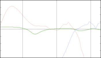
Nowadays, we do things a little differently, the measurements that are performed in the listening window (between 10 and 20 measurements in total) are compared and analysed for common aspects in their time responses. In other words, we’re checking to see whether the loudspeaker has natural resonances in it that causes it to “ring” in time (just like a bell rings when you hit it). Ringing is a natural behaviour of a loudspeaker, but that doesn’t mean it’s a good thing – it means that some frequency (the one that’s ringing) lasts longer than the others when you hit the loudspeaker with a signal (usually it’s ringing at lots of different frequencies). Depending on what frequencies are ringing, the result could be a “muddy”- or a “harsh”-sounding loudspeaker (to name just two of many descriptors meaning “bad”…) If we can see the same ringing in all (or at least most) of the measurements in the listening window, then the DSP engineer working on the project will make a filter for the signal processing that makes the ringing go away – in essence, we make the signal that we’re sending into the loudspeaker ring opposite to the natural ringing of the loudspeaker itself. You can think of it like kicking your legs in the wrong direction when you’re on a swing to make yourself slow down – you’re actively working in the opposite direction of the natural resonance of the system (where you-on-the-swing is “the system”).
In addition to making the resonances go away, we add filters to
- push the low frequency response to go as low as we want it to
- ensure that the loudspeaker drivers (for example, the woofer and the tweeter) meet each other correctly through the crossover and work together instead of against each other. In order to do this correctly, you can’t just build a crossover – you have to incorporate the natural frequency responses of the loudspeaker drivers as part of the total filter design.

At the end of this process, we have a loudspeaker that has a final response that has been corrected so that it measures well inside the listening window. We also have a bunch of measurements that we’ll probably come back to later.

Step #2: Tuning
The prototype with its correction filters are brought into the listening room and we start playing music through it. The first thing to do is just sit and listen using recordings that we know really well (usually, for me, that means starting with “Bird on a Wire” by Jennifer Warnes from Famous Blue Raincoat – I’d guess that I have heard that song, on average, once a day, every day, since about 1990 or so). Pretty soon, some problem will be apparent. Depending on the problem that shows up, we’ll try to fix it by correcting the physical reason for the problem. (This is done by the acoustical engineer working with the mechanical engineers to sort out where the problem occurs and how to fix it.) For example, if a part of the loudspeaker cabinet is vibrating and “singing along” with the loudspeaker, we’ll stiffen the cabinet, either by increasing its thickness, or changing the material it’s made out of, or adding ribs or bulkheads or some combination of those things. Once that problem is fixed, we bring it back into the listening room, find another problem, fix it, listen, complain, fix, listen, complain, fix, rinse, repeat, etc. etc…
Eventually, once all of the problems that we can fix with physical corrections are done, we start the next phase of the tuning. This is where the “design” part of the sound design comes in…
We set up the loudspeaker with its correction filters and its physical improvements in the listening room and start listening to music again. Now, if something sticks out as sounding wrong in the recording, we use an equaliser to correct it. If a note is sticking out that shouldn’t be, then we put in a dip in the equalisation to reduce the problem. If there’s some frequency band that seems to be missing, then we’ll use an equaliser to boost it a little to get it back. Typically, that process takes about 3 to 5 days in the listening room, and at the end, we have something between 20 and 40 extra equalisers in the signal flow. When that’s done, we pack up and go to a different listening room and start the process from scratch again. A couple of days later, we have another 20 – 40 filters. Then we pack up and go to a different room and start again. That process is done in something like 4 or 5 rooms, depending on the loudspeaker that we’re working on. Usually, we try to use rooms that are different from reach other, but also that will be representative of the acoustic behaviours of the rooms that the products will be used in. For example, when we were tuning the BeoPlay A9, one of the “rooms” was outdoors in the acoustical engineer’s back yard. This was because some customers will put their A9 out on the back deck or by the pool – so we used that situation as one of our tuning rooms.
So, now we have 4 or 5 sets of tunings, each with about 30 equalisers in them (give or take…). These tunings are then analysed to see what is common amongst them. You see, if we were to just tune a loudspeaker in a single position in a single room, a big part of the tuning would be there to correct the acoustical behaviour of the room. For example, in our main listening room in Struer, we have a pretty nasty room mode that rings at about 55 Hz. Whenever I tune a loudspeaker in that room, I put in a notch filter at 55 Hz to reduce the audibility of the problem (especially since I start tuning using Bird on a Wire, and it’s in A Major, and 55 Hz is an A). However, if your living room is not the same size as Listening Room 1 in Struer, then your room modes will be at different frequencies, so you should have a notch filter at those frequencies instead of 55 Hz. So, in order to eliminate the individual corrections for the individual rooms that we used for tuning the loudspeaker, we just take the common aspects from each tuning. For example, if the first tuning has a dip at 55 Hz and a boost at 200 Hz, and the second tuning has a dip at 65 Hz and a boost at 200 Hz – we only keep the 200 Hz boost (since the notches at 55 Hz and 65 Hz are probably due to the rooms, not the loudspeaker itself).
Once the common aspects of all those tunings have been extracted, we use those to build an equalisation that is, essentially, the sound design. That equalisation is built into the loudspeaker, and we start getting more people to listen to it in more rooms (for example, we’ll send people home with prototypes that include the sound design tuning to get “real world” testing).
Why do you need Sound Design?
Of course, there are purists amongst you who will ask why it is that we need the sound design process in the first place. The logic goes that if you make a loudspeaker with a razor-flat on-axis frequency response, then you will get a perfect loudspeaker – end of story. Anything that is done afterwards to muck about with that response is just ruining the loudspeaker. Ignoring a lot of details, this would be true if you used your loudspeaker in a room that had no reflections – in other words, if all you hear is the on-axis sound, and all of that energy that goes in all other directions never reflects off of anything else and bounces back at you, then a flat on-axis response would probably be a good idea.
However, think back to where we started. We said that the power response of the loudspeaker is at least as, if not more, important than the on-axis magnitude response. This means that the sound that radiates away from the loudspeaker in directions other than yours is what you hear most of the time. The relationship between the on-axis magnitude response and the power response is determined by the physical shape of the loudspeaker and its components (as well as the frequencies of the crossovers). And, how that balance between the on-axis response and the power response is perceived at the listening position (wherever that might be…) is really unpredictable. So, rather than building a tuning that is based on a prediction, we experience it instead – by playing the loudspeaker in different rooms and different positions and assembling some sort of average behaviour in the real world.
One of the statements I’ve made on Bang & Olufsen marketing materials in the past (like this video, for example) is that, when you sit in your living room and listen to a pair of B&O loudspeakers, you should hear what the mastering engineer (or the mixing engineer, or the recording engineer) heard when he or she did the recording using professional studio monitor loudspeakers in a mastering or recording studio. (Note that this is very different from the philosophy that you should be able to sit in your living room, close your eyes, and be fooled into thinking that the musicians are standing in front of you. In my opinion this is a silly philosophy, akin to believing that you should go to a movie theatre and believe that you’re in the movie instead of watching it. A music recording should be better than real life – not the same as it. And, please – before you write a comment below telling me that I’m wrong, read this first – then this – and then come back and write a comment below telling me that I’m wrong.) However, since your living room is not a mastering studio, it doesn’t make sense for you to use studio monitors. In other words, the goal is that the combination of B&O loudspeakers and your living room should be the same as studio monitors and a recording studio.
So, the moral of the story is that the goal of sound design (at least at Bang & Olufsen…) is to ensure that our loudspeakers in a normal room (whatever that means for a given product) sounds like professional studio monitors in a recording studio. In other words, if we started making studio monitors instead of home loudspeakers, I’d be out of a job, since we wouldn’t need a sound design procedure to “undo” the effect the room has on our loudspeakers…
P.S
One thing that I did not talk about here (mostly just to keep things clear) was the off-axis responses of the loudspeaker, the collection of which comprises its directivity. That discussion will be left for a future posting.
P.P.S.
There is one aspect of this article that can explain one issue that some people have with B&O loudspeakers. If you take a look at some magazine reviews and some comments from people-who-post-opinions-about-loudspeakers-late-at-night-on-Internet-fora, they’ll say that our loudspeakers are obviously not worth anything, since they do not have a flat on-axis frequency response. Of course, if the only criterion you use to define what makes a loudspeaker “good” is a one-dimensional measurement at a single point in space, then you might be inclined to agree with that opinion.
However, if, like me, you live in three dimensional space in a house that has walls, floors and ceilings – and you have more than one chair and possibly even a friend or two – you might be inclined to think differently…
Florent Gatin says:
Great article Geoff, really inspiring.
What importance do you attach to drivers’ quality ?
Is it necessary to have a driver’s frequency response that is perfectly flat from the beginning (within the driver’s frequency band) or can the tweaking (equalizers) compensate for a more uneven (and cheaper) driver ?
geoff says:
Hi Florent,
Basically speaking, we can take a loudspeaker’s characteristics and divide them into two categories: Linear and Non-linear behaviour. The Linear behaviour is the frequency response and the directivity (assuming that these do not change with level). The Non-linear behaviour is the distortion that it produces, which is usually very closely related to the level at which you’re playing signals.
If you have a driver that is very linear, AND if you have control of the driver over a wide range of signal levels (i.e. you have a wide “Bl curve”) then it is relatively simple to compensate for some of its linear characteristics using processing. For example, the frequency response is easily correctable – however, the directivity cannot be changed, since this is due to the physical shape of the front of the driver and the cabinet it’s in.
If you have a driver that is very non-linear, then compensating for its problems is either problematic or impossible. For example, if you have reached the maximum excursion of the driver, you cannot compensate for the resulting “clipping” by driving it harder.
So, the answer is “it depends” – specifically on the characteristic that you want to fix.
I would, however, say that, I would not blame the frequency response on the price of the driver. There are some cheap drivers that (although they might have higher distortion) have a pretty good on-axis magnitude response. I have seen expensive drivers that have nastiness in the on-axis magnitude response (although they might have lower distortion).
It depends…
Cheers
-geoff