#19 in a series of articles about the technology behind Bang & Olufsen loudspeakers
If you take a careful look around the connection panel of almost any Bang & Olufsen loudspeaker, you’ll find a three-position switch that is labelled something like “Free / Wall / Corner” or “F / W / C” or “Pos 1 / Pos 2 / Pos 3”. What does this do and how should you use it?
Part 1: Unreal acoustics
Let’s pretend that you have a loudspeaker that is perfectly omnidirectional, and it is in a free field (meaning that the sound that radiates from it is free to propagate forever without hitting anything – in other words, it’s floating in infinite space). Let’s then say that we measure the magnitude response of that loudspeaker and we find out that it has a perfectly flat response from 0 Hz to infinity Hz. Remember that the source is perfectly omnidirectional, so the response will be the same regardless of which direction you measure it from. This also means that if you do a lot of magnitude response measurements around the source and average them, it will also be flat, since the average of a whole bunch of the same thing is the same as any one of the things (i.e. the average of 5 & 5 & 5 & 5 & 5 & 5 & 5 is 5).

Now let’s divide the infinite space in half with a very large, perfectly flat wall that extends infinitely – and we’ll put it fairly close to the loudspeaker. Now, if we do a magnitude response measurement at one position, we’ll see a response that is comprised of alternating boosts and cuts as we go up in frequency. This is caused by the interference between the direct sound of the loudspeaker and its reflection off the wall. These two sounds arrive at the measurement microphone at two different times – which means that different frequencies will be separated in phase differently. The higher the frequency, the greater the phase difference between the direct and reflected sounds. And, depending on the phase at any one frequency, the result may either be constructive interference (where the two signals add) or destructive interference (where they cancel each other). If it helps, an easier way to think of this is that the wall is a mirror that results in a reflection of the loudspeaker on the other side of it. The sound that arrives at the microphone is the combination of the two loudspeakers (the real one and the one on the other side of the mirror). If we do an averaged pressure response measurement, the averaging that we have to do results in the fact that we lose the phase information in each of our individual measurements. However, each individual response that we measure has peaks and dips that affects how it adds to the other responses. In the very low frequencies the “two” loudspeakers are very close together relative to the very long wavelengths of low frequencies in air – so they add together almost perfectly. This means that the total output will be doubled at the very low end – 200% of the output (or 6 dB more) than without the wall. At very high frequencies, the outputs of the two loudspeakers add randomly – sometimes increasing, sometimes cancelling the total. The end result of this average is a messy response, but is roughly the same level as 141% (or 3 dB more) than if the wall weren’t there. (Note that the low end is 2 times louder, (because there are two “sources” – the real one and the reflected one. However, the high end is 1.41 times louder. 1,41 is the square root of 2 – the reason for this involves an explanation of power being proportional to the square of the pressure, so doubling the power results in multiplying the pressure by sqrt(2).) Take a look at Figures 2 and 3. You’ll see that the result of placing the theoretical wall near the theoretical loudspeaker is that the low end and the high end are boosted – but the low end is boosted about 3 dB more than the high end. If you compare Figures 2 and 3, you’ll see that the closer the loudspeaker is to the wall, the higher the top frequency of the “low end”.

If you divide space once more, using a second wall that is perpendicular to the first (so now your speaker is on the floor, next to a wall, for example), you are doubling the number of “loudspeakers” again. Now we have one “real” loudspeaker and 3 reflections. Let’s forget about the magnitude response at one location for now and just deal with the power response, since that’s a little less complicated. Now we have 4 times the output (or 12 dB more) in the low frequencies and, 2 times the output (or 6 dB more) in the high frequency ranges. (Notice again that the multiplier for the output in the low end is the number of loudspeakers – either real or reflected – and that the multiplier for the output in the high frequencies is the square root of that number.)


Finally, let’s add one last wall, perpendicular to the other two (i.e. two walls and the floor). This resuts in a total of 8 sources (one real and 7 reflected) which means that the output will be 8 times louder (or 18 dB) in the low end (than if the walls weren’t there) and 2.8 (sqrt(8)) times louder (or 9 dB) in the high end.


So, the first lesson to be learned here, for now, is that, in a theoretical world, where loudspeakers are perfectly omnidirectional and walls go forever, the more walls you have the bigger the bass boost. (Of course, you’ll also get a boost in the high end, but it will be smaller than the low-end boost, and you’ll probably compensate for that with the volume knob when the vocals and snare drum come in…) There is a second, nearly-as-important lesson. Look carefully, for example, at Figures 7 and 8. Starting in the low end, you can see the bass boost resulting from the collective reflections off the two walls. As you go up in frequency, you can see that the boost drops. However, before it levels out (albeit messily) at the high end, you can see that there is a deep drop in the level (i.e. in Figure 8, it’s at 100 Hz). This is because, for the particular wall distances we’re looking at, there is more cancellation of signals going on than there is constructive interference. So, the average is lower than if the walls weren’t there. This will be important later…
Part 2: Increasingly realistic acoustical behaviour
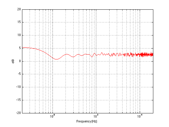
We can then take it one step further and consider that the very pretty graph shown in Figure 1 is extremely theoretical. A free field is an imaginary space – the reality is that a “free standing” loudspeaker is not really in a free field. For starters, it has to stand on something (unless you’re hanging it from the ceiling) – so the floor is not very far away – probably 1 m or so. Secondly, unless you live in a VERY large house, even when the loudspeaker is placed far from a wall, it’s probably not going to tens of metres away from any way. We can set a limit of something like 1 m on this – meaning, if you’re more than 1 m from any wall, we’ll call that “free”. This means that, in a real space, where the loudspeaker is at least 1 m from any surface, the response you get as a result of those three adjacent walls is roughly like the graph shown in Figure 8. The implications of this previous paragraph, in the real world, are important. What this means is that, when we do the sound design for a loudspeaker, we have to choose its position in a room rather carefully. Typically, it’s in a “free” position, which means, in a real world, about 1 m from each of the two adjacent walls (this isn’t measured exactly – everything in this article should be considered to be approximate). (Of course, loudspeakers that are, in all likelihood destined for a wall bracket are tuned on a wall instead.) So, the “free” position isn’t the same as the theoretical free field in Figure 1. It’s more like the not-very-close-to-a-surface case shown in Figure 8. The behaviour of the loudspeaker in this location is then the “reference” – the goal is then to ensure that, if a customer places the same loudspeaker against one wall or in a corner of two walls, the loudspeaker will sound the same as it does in the reference position. We do this by looking at the difference between the averaged response of the loudspeaker in the “wall” or “corner” location and the reference “free” position. For example, if we were making perfectly omnidirectional loudspeakers, and we say that 30 cm from a wall is close enough to call the loudspeaker in a “wall” position, then we would subtract the response curve shown in Figure 8 (the reference “Free” response) from the response shown in Figure 4. This difference, shown in Figure 9, below, is the “eq curve” applied to a loudspeaker that is placed closer to a wall. So, you can see that we get a large bump in the low end (in this case, with these dimensions) around 100 Hz, and dips below and above this peak (at 20 Hz and around 400 Hz).

If we were making perfectly omnidirectional loudspeakers, and we compare a “corner” position 30 cm from three perpendicular wall, then we would subtract the response curve shown in Figure 8 (the reference “Free” response) from the response shown in Figure 7. This difference, shown in Figure 10, is the “eq curve” applied to a loudspeaker that is placed closer to a wall. So, you can see that we get a larger bump in the low end (in this case, with these dimensions), still around 100 Hz, and a dip above this peak (at around 300 Hz).

So, this means that, for these perfectly omnidirectional loudspeakers, considering only these dimensions, the equalisation filters we would have to apply to the loudspeaker to compensate for a “wall” or “corner” position would have to be the inverse of the curves in Figures 9 and 10. In other words, we would just flip them upside down to undo the change in the loudspeaker’s timbre as a result of its placement. However, in real life, loudspeakers are not omnidirectional at all frequencies. In real life, they don’t even have the same directional characteristics (omnidirectional or not…) as themselves at all frequencies. Due to their physical shape, the size of the loudspeaker drivers and the choice of crossover frequencies (amongst other things…) a typical loudspeaker will radiate different frequencies at different levels in different directions – even if it has been equalised to be perfectly flat on-axis in a free field. In addition, additional (perhaps unwanted) moving “parts” such as air flow in and out of a port, a slave driver or even a moving panel in the loudspeaker cabinet (see this article for a discussion about this) will not only affect the magnitude of a signal in a given direction, but also its phase relative to the on-axis response. So, what impact does reality have on the rule-of-thumb lessons learned above? Let’s take an only-slightly-more realistic example of a loudspeaker that is omnidirectional in the low frequency bands and very directional in the mid and upper frequency bands. Now, the energy in the low end will radiate forwards and backwards, reflecting off the wall (or walls) and still resulting in a boost. However, since the high frequency bands are not omnidirectional, you won’t get a boost from the reflections in the power response of the loudspeaker in the room. Consequently, the bass boost caused by the presence of the walls will be exaggerated due to the difference in directivity of the loudspeaker in different frequency bands. Of course, the actual directivity of a loudspeaker is considerably more complicated and messy than a simple description like “omni in the low end and beaming in the high end” – but we won’t delve very far into the details of that in this article. Let’s just stop at “real life is complicated”. The end result of this is that, if we do the same math as I used to do the plots shown above, but we include the actual directivity measurements of the actual loudspeaker, then we can calculate the final equalisation curves that we need to make the wall and corner positions sound more like the free position. An example of these curves are shown below in Figure 11. Note that these curves are applied to the “free” setting which, in the case of this loudspeaker, is the reference position in which it was tuned during the sound design process. The two things to note here are the dip at around 100 Hz which counteracts the boost that we see in the theoretical curves in Figures 9 and 10. There is also a slight boost around 200 Hz which compensates for the dip that can be seen in Figures 9 and 10. The very low end is untouched, since there is very little difference in the extreme low end of the loudspeaker. This is because, in a normal room, you can’t get far enough away for the walls to “not exist” at 20 Hz – the wavelength of the very low end is just too big.

So, as you can see, the “Free / Wall / Corner” position switch, supplied on almost all Bang & Olufsen loudspeakers, is not merely a simple shelving filter with a 3 dB or 6 dB difference on the low end. It’s a rather complicated filter that is customised for each loudspeaker that we make, since it is dependent on the specific directional characteristics of that loudspeaker.
Jiahe Liu says:
Hi Geoff,
Thanks for this great post. I got a question:
You said that you use the sound design position as the reference “free” position. And in a previous post you also said that you do the sound design in many different rooms. However in different rooms the loudspeaker might have different responses, so there is more than one “reference free location”. how does this work? Does it means that in different rooms you always put the loudspeaker 1 meter from side walls so the reference responses (figure 8) are more or less the same?
thanks,
Jiahe
geoff says:
Hi Jiahe,
When I do the sound design in the 4-5 rooms, the equalisation that has been put in the loudspeaker is the result of the measurements done in the Cube. When I’m working on the loudspeaker in those rooms, I typically place it in a position that would be considered as “free” – away from walls. However, I do NOT try to duplicate the distance to the walls. The point of going from room to room (and sometimes, different positions in the same room) is to randomise the acoustical coupling to the space as much as is pragmatically feasible. So, in fact, I try to use rooms that are different from each other, and positions that are also different from each other…
In theory, this means that anything that is common in the sound designs that are produced in those rooms has something to do with the loudspeaker (or me) – and not the rooms or the placement.
This info is then used to create the “Free” setting. The “Wall” and “Corner” compensation equalisations can be created using the 3-dimensional sets of measurements, since we can calculate the effects of one or two walls on the radiated response of the loudspeaker in the remaining 1/2 space or 1/4 space.
Cheers
-geoff
Jiahe Liu says:
Hi Geoff,
thanks for the quick reply.
I understand that the “wall” and “corner” response can be measured, but the equalisers should be their difference between the “free” position. And the “free” position (where the sound design was made) is not unique, so how a compensation filter can be made?
for example in figure 11, there is a dip in 100 Hz. As I understand it is come from a dip in just one free position (figure 8). However the sound design is made in multiple rooms, so the 100 Hz dip is probabily not considered in the “free” setting. so, why the “wall’ and “corner” filters are compensiting that 100 Hz dip?
best regards,
jiahe
geoff says:
Hi Jiahe,
The “Free” position is the reference position, and the other two equalisations are created as offsets to that. So, the 100 Hz dip in figure 11 is the dip that is required to change the reference equalisation (the “free” setting) into one that is tailored to a loudspeaker position that is closer to a wall.
Consider a simple case:
– we only think in 2 dimensions – the horisontal plane, in this example
– you have a loudspeaker that has a perfectly flat on-axis response in a free field
– it has a perfectly omnidirectional directivity up to (but not including) 100 Hz
– it has a perfectly semicircular directivity from -90º to +90º (and no radiation at all behind the loudspeaker) from 100 Hz and up.
If you put this loudspeaker in a free field and measure on-axis, you will get a flat magnitude response.
If you put this loudspeaker very close to an infinitely stiff infinite wall (placed directly behind it) and measure again, you’ll get a 6 dB boost from 100 Hz and down. This is because, below 100 Hz, the front radiation sums with the reflected rear-ward radiation and you get 2x the output (20*log10(2) = 6.02 dB)
So, to make a “wall” equalisation for this loudspeaker, you would need to drop everything below 100 Hz by 6 dB.
If you put this loudspeaker in a corner made of two infinitely stiff infinite walls (where the loudspeaker is aimed diagonally out of the corner) and measure again, you’ll get a 9.5 dB boost from 100 Hz and down. This is because, below 100 Hz, the front radiation sums with the rear-ward radiation reflected off the two walls and you get 3x the output – one direct sound and two reflections. (20*log10(3) = 9.54 dB)
So, to make a “corner” equalisation for this loudspeaker, you would need to drop everything below 100 Hz by 9.5 dB.
This is a very simple, two-dimensional example, but the illustration holds.
In the real world, we have a loudspeaker that has some on-axis magnitude response and some associated 3-dimensional power response. Those two are balanced for a real-world use in using an equalisation we call the “sound design” of the loudspeaker (instead of targeting a flat magnitude response in a free field). That tuning is designed to be applicable to multiple rooms, but in a “free” position in those rooms.
Knowing the frequency-dependent three-dimensional directivity of the loudspeaker, we can calculate the effects of placing the loudspeaker close to one or more surface at various distances. Apart from changes in coupling to the room modes, those “effects” are relatively independent of the room itself. They are, however, dependent on the (frequency dependent) impedances of the boundaries, and, in extreme cases, the rotation of the loudspeaker with respect to the boundaries. Since we can calculate these effects on the magnitude response, we can create a compensating filter that is added in series to the sound design equalisation of the loudspeaker, thus “undoing” the effects of the loudspeaker placement with respect to the local boundaries, but maintaining the compensation for the room response.
So, for example, the 100 Hz dip in Figure 11 is applied in addition to the “free” equalisation – which can be anything…
I hope that this clears things up.
Cheers
-geoff
Jiahe Liu says:
thanks Geoff, now i understand that the room modes are not considered here and we are only talking about the “boundary” effects. But i’m still a little bit confused…
the “wall’ and “corner” response can be calculated from the directivity measurement combined with some simulation method. I suppose the model is three infinite walls that are perpendicular to each other.
To “compensate” them, you need to know the response of a “free” position. Unlike the “wall” and “corner”, which can be easily defined in the model, the “free” position is not unique in the model. So how can you calculate their differences and make a compensate curve?
best regards,
Jiahe
geoff says:
Hi again,
This is incorrect. You don’t need to know the response in the free position to do the compositions for the “wall” and “corner” offsets, since they are independent of the “free” equalisation.
Cheers
-geoff
Jiahe Liu says:
thanks goeff!