Part 1
Part 2
Part 3
Part 4
Part 5
Part 6
Part 7
Part 8a
Part 8b
Part 9
If you read about high resolution audio – or you talk to some proponents of it, occasionally you’ll hear someone talk about “temporal resolution” or “micro details” or some such nonsense… This posting is just my attempt to convince the world that this belief is a load of horse manure – and that anyone using timing resolution as a reason to use higher sampling rates has no idea what they’re talking about.
Now that I’ve gotten that off my chest, let’s look at why these people could be so misguided in their belief systems…
Many people use the analogy of film to explain sampling. Even I do this – it’s how I introduced aliasing in Part 3 of this series. This is a nice analogy because it uses a known concept (converting movement into a series of still “samples”, frame by frame) to explain a new one. It also has some of the same artefacts, like aliasing, so it’s good for this as well.
The problem is that this is just an analogy – digital audio conversion is NOT the same as film. This is because of the details when you zoom in on a time scale.
Film runs at 24 frames per second (let’s say that’s true, because it’s true enough). This means that the time between on frame of film being shot and the next frame being shot is 1/24th of a second. However, the shutter speed – the time the shutter is open to make each individual photograph is less than 1/24th of a second – possibly much less. Let’s say, for the purposes of this discussion, that it’s 1/100th of a second. This means that, at the start of the frame, the shutter opens, then closes 1/100th of a second later. Then, for about 317/10,000ths of a second, the shutter is closed (1/24 – 1/100 ≈ 317/10,000). Then the process starts again.
In film, if something happened while that shutter was closed for those 317 ten-thousandths of a second, whatever it was that happened will never be recorded. As far as the film is concerned, it never happened.
This is not the way that digital audio works. Remember that, in order to convert an analogue signal into a digital representation, you have to band-limit it first. This ensures (at least in theory…) that there is no signal above the Nyquist frequency that will be encoded as an alias (a different frequency) in the digital domain.
When that low-pass filtering happens, it has an effect in the time domain (it must – otherwise it wouldn’t have an effect in the frequency domain). Let’s look at an example of this…
Let’s say that you have an analogue signal that consists of silence and one almost-infinitely short click that is converted to LPCM digital audio. Remember that this click goes through the anti-aliasing low-pass filter, and then gets sampled at some time. Let’s also say that, by some miracle of universal alignment of planets and stars, that click happened at exactly the same time as the sample was measured (we’ll pretend that this is a big deal and I won’t suggest otherwise for the rest of this posting). The result could look like Figure 1.
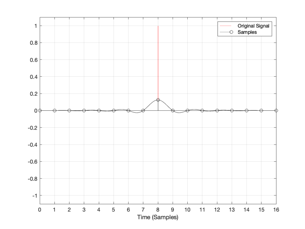
If I zoom in on Figure 1 vertically, it looks like the plot in Figure 2.
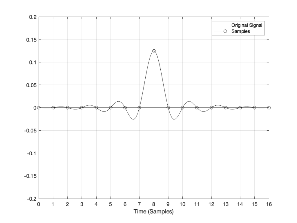
There are at least three things to notice in these plots.
- Since the click happened at the same time as a sample, that sample value is high.
- Since the click happened at the same time as a sample, all other sample values are 0.
- Once the digital signal is converted back to analogue later (shown as the black line) the maximum point in the signal will happen at exactly the same time as the click
I won’t talk about the fact that the maximum sample value is lower than the original click yet… we’ll deal with that later.
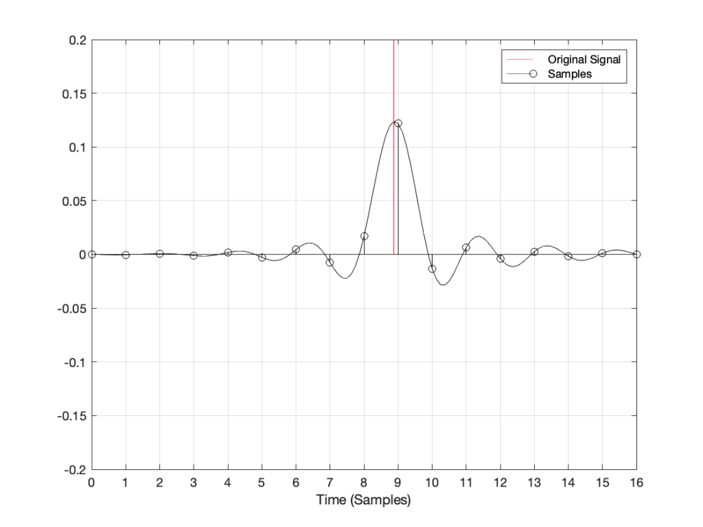
Now, what would happen if the click did not occur at the same time as the sample time? For example, what if the click happened at exactly the half-way point between two samples? This result is shown in Figure 3.
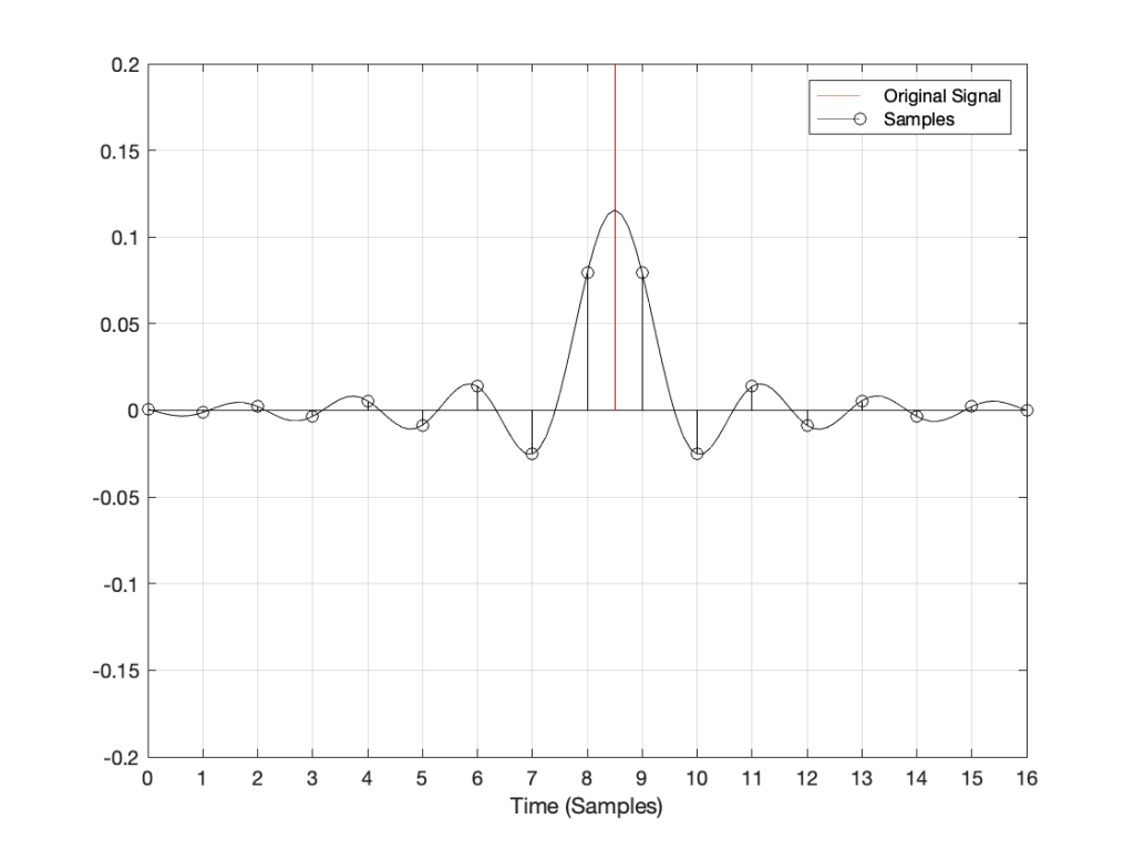
Notice now that almost all samples have some non-zero value, and notice that the two middle samples (8 and 9) are equal. This means that when the signal is converted to analogue (as is shown with the black line) the time of maximum output is half-way between those two samples – at exactly the same time that the click happened.
Let’s try some more:
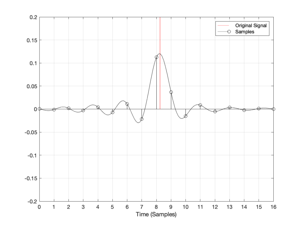
I could keep doing this all night, but there’s no point. The message here is, no matter when in time the click happened, the maximum output of the digital signal, after it’s been converted back to analogue, happens at exactly the same time.
But, you ask, what about all that “temporal smearing” – the once-pristine click has been reduced to a long wave that extends in time – both forwards and backwards? Waitaminute… how can the output of the system start a wave before something happened?
Okay, okay…. calm down.
Firstly, I’ve made this example using only one type of anti-aliasing filter, and only one type of reconstruction filter. The waveforms I’ve shown here are valid examples – but so are other examples… This depends on the details of the filters you use. In this case, I’m using “linear phase” filters which are symmetrical in time. I could have used a different kind of filter that would have looked different – but the maximum point of energy would have occurred at the same time as the click. Because of this temporal symmetry, the output appears to be starting to ring before the input – but that’s only because of the way I plotted it. In reality, there is a constant delay that I have removed before doing the plotting. It’s just a filter, not a time machine.
Secondly, the black line is exactly the same signal you would get if you stayed in the analogue domain and just filtered the click using the two filters I just mentioned (because, in this discussion, I’m not including quantisation error or dither – they have already been discussed as a separate topic…) so the fact that the signal was turned into “digital” in between was irrelevant.
Thirdly, you may still be wondering why the level of the black line is so low compared to the red line. This is because the energy is distributed in time – so, in fact, if you were to listen to these two clicks, they’d sound like they’re the same level. Another way to say it is that the black line shows exactly the same as if the red curve was band-limited. The only thing missing is the upper part of the frequency band. (You may notice that I have not said anything about the actual sampling rate in any of this posting, because it doesn’t matter – the overall effect in the time domain is the same.)
Fourthly, hopefully you are able to see now that an auditory event that happens between two samples is not thrown away in the conversion to digital. Its timing information is preserved – only its frequency is band-limited. If you still don’t believe me, go listen to a digital recording (which is almost all recordings today) of a moving source – anything moving more than 7 mm will do*. If you can hear clicks in the sound as the source moves, then I’m wrong, and the arrival time of the sound is quantising to the closest sample. However, you won’t hear clicks (at least not because the source is moving), so I’m not wrong. Similarly, if digital audio quantised audio events to the nearest sample, an interpolated delay wouldn’t work – and since lots of people use “flanger” and “phaser” effects on their guitar solos with their weekend garage band, then I’m still right…
The conclusion
Hopefully, from now on, if you are having an argument about high resolution audio, and the person you’re arguing with says “but what about the timing information!? It’s lost at 44.1 kHz!” The correct response is to state (as calmly as possible) “BullS#!T!!”
Rant over.
* I said “7 mm” because I’m assuming a sampling rate of 48 kHz, and a speed of sound of 344 m/s. This means that the propagation distance in air is 344/48000 = 0.0071666 m per sample. In other words, if you’re running a 48 kHz signal out of a loudspeaker, the amplitude caused by a sample is 7 mm away when the next sample comes out.
Thought another way, if you have a stereo system, and your left loudspeaker is 7 mm further away from you than your right loudspeaker, at 48 kHz, you can delay the right loudspeaker by 1 sample to re-align the times of arrival of the two signals at the listening position.