#49 in a series of articles about the technology behind Bang & Olufsen loudspeakers
Once-upon-a-time, I wrote an article in this series about how a loudspeaker driver is made and (to some extent) how it works. Just recently, a reader asked a question related not only to this topic, but specifically to the BeoLab 90. Teddy wrote:
I am very curious as to why a driver like a Scanspeak Illuminator can reproduce so much more detail of the original signal when the fundamental design principles are just like less expensive drivers. I guess my question is how is a driver with superior detail retrieval designed and constructed? Also, what other benefits do you see when working with high end drivers?
I’m not sure that I can answer this question directly – but, in thinking about an answer, I realised that it might be interesting to talk about one reason why one loudspeaker driver is chosen over another in a given application or project.
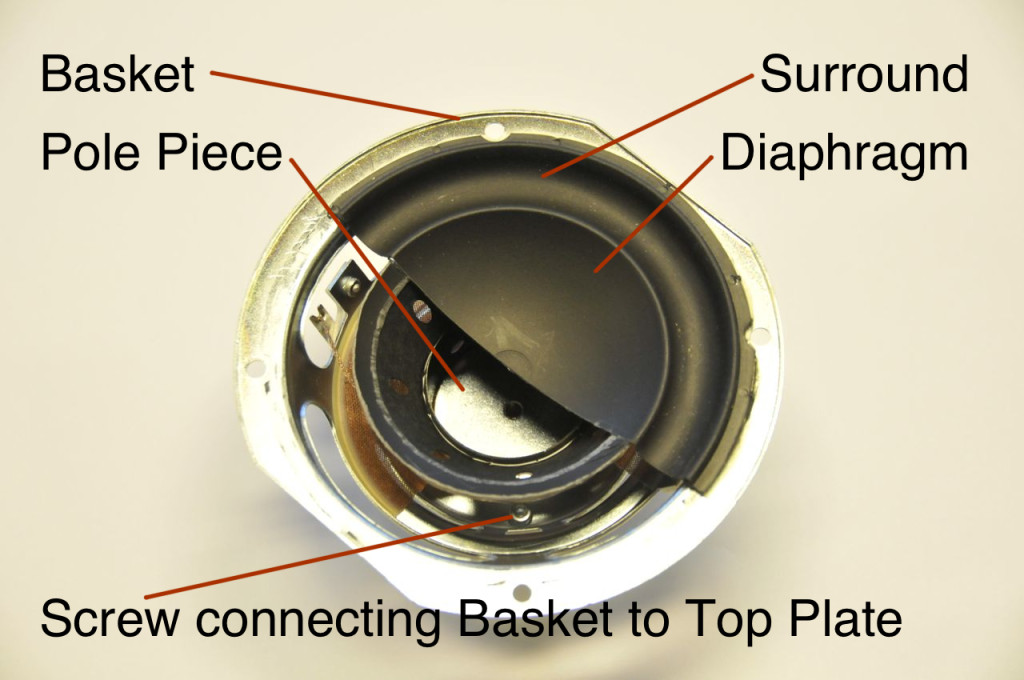
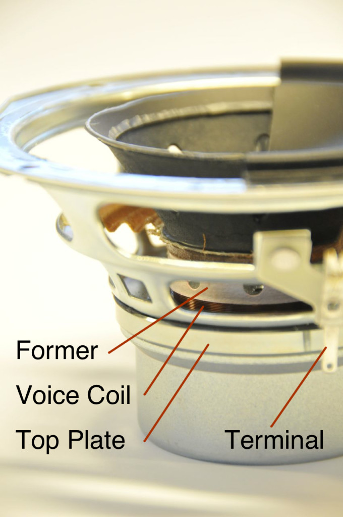
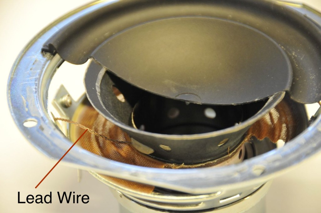
A quick background sidebar: a moving coil dynamic loudspeaker driver is a device that converts an electrical signal into mechanical movement. A voltage is applied to the terminals which causes current to flow through the voice coil (which is wrapped around a tube called a “former” that is attached to the “diaphragm” or “cone” – see Figures 1, 2, 3, and 4, below). That current generates a magnetic field around the wire – and since the coil is sitting in the magnetic field of a permanent magnetic, it wants to move. Depending on the direction of the current, the voice coil will either push outwards or pull inwards resulting in some excursion of the voice coil, former and diaphragm (those parts are all glued together). The whole thing doesn’t fly off because it’s held back by the loudspeaker’s “suspension”. The suspension is comprised of two things – the “surround” (usually a rubber ring that connects the edge of the diaphragm to the top of the basket – the metal frame that supports the whole assembly) and the “spider” (a ring of stretchy fabric that connects the former to the basket). The reason there are two components to the suspension is to ensure that, when the diaphragm moves in and out, it doesn’t rock from side to side. If you want a more complete version of this story, read this article.
When building any loudspeaker, you have to make some decisions about which driver to use. Lots of factors come into this decision – frequency range, maximum sound pressure level (vs. frequency), directivity (vs. frequency), size, sensitivity, cost, and many more things are weighed in order to make the most appropriate choice for the product. (If you’re making a passive loudspeaker, then the frequency response of the driver is important – but if you’re making an active loudspeaker, particularly one that is DSP-based, this is less of a concern, since it can be fixed (more or less…) in the processing.) One of the more significant issues in this list that an acoustical engineer worries about is the nonlinear distortion characteristics of the driver. (This is a big concern with a DSP-based active loudspeaker because non-linear distortion cannot be fixed in the processing.) If the movement of the driver’s diaphragm isn’t the same shape as the electrical signal that you put into it (for example, if you apply a nice smooth electrical sine wave at the speaker terminals, but the diaphragm moves in a jerky square wave fashion, then the output of the speaker isn’t the same as the input) then the signal has been distorted. There are different types of distortion, so we have to be a little more specific.
Linear distortion is what you have when the change to the signal can be “undone”. For example, if you add bass to a signal, then you’ve distorted it (the output of the bass boost is not the same as the input – but that’s the point). However, if you remove bass from the result, you can (in theory) get back what you started with.
Non-linear distortion is what you have when the change to the signal cannot be undone. If you put in a sine wave and the system clips (“chops off”) the top of it, there’s no way of regaining the nice smooth wave that you started with, because there’s no way of knowing what was there before the signal was chopped off.
Non-linear distortion can be generally broken into two general headings: harmonic distortion (sometimes abbreviated THD for Total Harmonic Distortion) and intermodulation distortion (or IMD). Harmonic distortion happens when you put in a signal with one frequency (say, a sinusoidal wave at 1 kHz) and you get out energy at other frequencies (that are multiples of the frequency of the input signal) as well (say, 2kHz, 3 kHz, 4 kHz, and so on…). Intermodulation distortion occurs when you put in more than one frequency (say, 900 Hz and 1000 Hz simultaneously) and you get out other frequencies that are usually mathematically related to the input (typically the sum and difference of multiples of the input frequencies – so, in our example, 1900 Hz (900+1000), 100 Hz (or 1000-900), 2900 Hz (2*1000+900), 1100 Hz (2*1000-900) and lots more…)
Another sidebar: These differences in distortion means that when you say “the signal sounds distorted” – the statement is about as useful as saying “the signal sounds different”. This is even true if you measure the distortion of a system and specify it with a number. See this posting and this posting for a more thorough discussion of this problem…
Back to our loudspeaker: in an ideal world, a loudspeaker driver’s movement would be an exact “replica” (more like an analogy) of the input signal. Sadly, this is never true. Never.
So, we start by accepting the knowledge that a loudspeaker driver is imperfect – and therefore it will impose some harmonic distortion and some intermodulation distortion on the signal. The next question is “why?” and “how can we minimise it?”
In order to talk about that, let’s take a driver and cut it in half. This is shown in Figure 4.
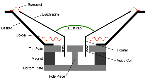
There are some moving parts of the loudspeaker driver. These are the diaphragm and dust cap, the former and the voice coil. these are all glued together and move as one part (hopefully…). When they move, the suspension (the surround and the spider) are stretched in one direction or the other. This can be seen in Figure 5.
Now, let’s pretend that the movement of the diaphragm (and the dust cap, former, and voice coil) is caused by you (instead of being moved by the voice coil) – you’re the one pushing and pulling the moving parts. When the diaphragm is at the rest position, it’s easy to move. However, as you push it further and further out, it becomes harder and harder to move, since the suspension is stretching more and more. (This is just like an elastic band – stretching it a little bit is easy, stretching it a lot is hard.) If you’re pulling the driver inwards, then it’s the same – the father you get from the rest position (the greater the excursion) the harder it is to move.
This behaviour is called the stiffness of the suspension (although it is also called the compliance – which is how not-stiff it is…). We can measure the suspension stiffness and plot it on a graph, relative to how far away the diaphragm is from the rest position (the excursion). An example of this is shown in Figure 6. (Note that Figure 6 is not the actual measurement of a real driver – I just drew a graph to illustrate the concept.)

There are two things to notice in the graph in Figure 6. The first is that, as the excursion of the diaphragm moves away from the rest position (either inwards or outwards) the suspension gets stiffer (or harder to move). This means that you need less force to move the diaphragm from 0 mm to 1 mm than you do from 5 mm to 6 mm. the second thing is to notice that the curve is not symmetrical. For example, when the diaphragm has moved outwards by 5 mm, the suspension is stiffer than it is if you move it inwards by 5 mm.
Both of these things will be important later.
Now let’s consider what’s really doing the pushing and pulling. As I described above, when we apply a voltage to the terminals of the voice coil, a current runs through it and it turns into an electromagnet with a magnetic field around it. If the current goes in one direction, one side of the coil is north and the other is south. If we reverse the current direction, we flip the polarity of the electromagnet. The voice coil is already sitting inside the magnetic field of a permanent magnet, so when it gets its own magnetic field it will try to move in one direction or the other, depending on which end is north and which is south (which are dependent on the direction of the current which is dependent on which loudspeaker terminal has the positive voltage and which has the negative.)
The bigger the difference in voltage we apply at the terminals, the greater the current through the voice coil, and the stronger the electromagnet. This means that we will be applying more force to move the voice coil (and the former, the diaphragm, and the dust cap) outwards or inwards.
However, there’s a problem in that last statement. We only have the force to move the voice coil if there’s a magnetic field (from the permanent magnet) to push against. If there were no permanent magnet, there would not be anything for the electromagnet (the voice coil) to push against, so it wouldn’t move.
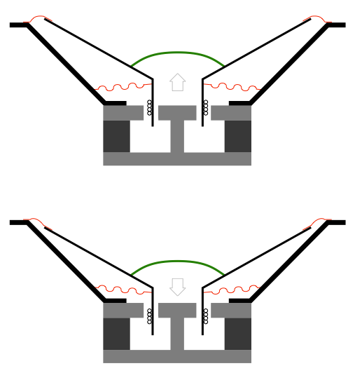
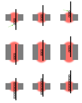
But look again – closely – at Figures 5 and 6. When the voice coil is at rest, it’s sitting in the “gap” which is where the magnetic field is strongest. However, as it moves inwards or outwards, it also moves out of the gap, and therefore out of the magnetic field. This is illustrated below in the three drawings in Figure 7.
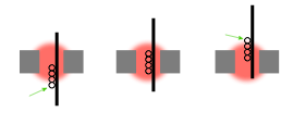
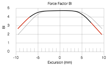
Look at the three drawings in Figure 7 which show that, as the coil moves inwards or outwards, part of the coil moves out of the magnetic field (green arrows), so there’s nothing for it to push against. This means that the bigger the excursion of the diaphragm, the less force with which you have to push (or pull) it. This force factor (abbreviated Bl – but we won’t talk about why…) is a product of the strength of the magnetic field, the length of wire in the coil. That value is multiplied by the amount of current flowing through the coil to find the force delivered by the system. However, as we can see above, is also dependent on the position of the voice coil relative to the gap. that change in force factor can be measured for the driver as a function of its excursion. An example of this is shown in Figure 8, below. (Note that Figure 8 is not the actual measurement of a real driver – I just drew a graph to illustrate the concept.)

Now, hopefully, you will be asking yourself a very important question. If you look at Figure 6, you can see that, as the excursion of the driver increases, the harder it is to move, so we should have more force factor available to move it. However, Figure 8 shows us that as the excursion of the driver increases we lose force factor… This is something like losing horsepower in your car’s engine every time you go up a hill…
Sadly, although the graphs I drew in Figures 6 and 8 are just invented curves that I drew, they’re not unusual to see… What’s the effect? Basically, it means that you don’t have the ability to push the driver as far out (or in) as you would like, so the peaks (and troughs) in your waveform will be flattened. If either the stiffness or the force factor curves (or both) are asymmetrical, then the flattening will be different on the outwards excursion than the inwards (in other words, the peaks will be squashed differently than the troughs). The total result is that the driver distorts the signals – and you’ll get both harmonic distortion and intermodulation distortion. The less flat the stiffness and/or force factor curves, the more distortion you’ll get. In addition, if you lose force factor with excursion, then when you have an impulsive sound (like a kick drum, for example), you can start moving the diaphragm outwards (because you have force factor at the rest position to do the throwing) but you don’t have the force factor to control its return – so you throw the speaker out, and hope that it comes back instead of pulling it back… This is another form of distortion – but it’s a time-based distortion that might look like “ringing” for example.
But what is it that you want?
In a perfect world, the stiffness of the suspension would be the same, regardless of the excursion of the driver – in other words, it would be a horizontal line instead of the curve in Figure 6. Also, in a perfect world, you would not lose force factor with excursion. In other words, you could always have the same amount of control over the driver, regardless of how far in or out it is.
In order to flatten the stiffness, we have to look at the behaviour of the surround and the spider (if we’re ignoring the effect of the air behind the driver in the loudspeaker enclosure, which, in a real world, cannot be ignored… but let’s stay out of the real world for the purposes of this discussion). One simple method of flattening the stiffness vs. excursion is to make the driver suspension to allow for a much bigger excursion than you expect, for example. If we look at the measured stiffness of the Scan-Speak Illuminator 12MU/4731T00 (the midrange driver in the BeoLab 90), it looks like the graph in Figure 9. (I traced this using the plot in this article.)
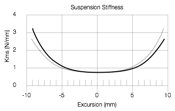
There are two things to notice about this stiffness curve. The first is how flat it is around the rest position. The second is that it’s very symmetrical, particularly around the rest position. (This is the reason the mirror image of the stiffness curve is plotted (in grey) – so that you can see the symmetry of the curve.) So, one reason we chose the Scanspeak Illuminator midrange for the Beolab 90 was for this stiffness curve. The “so what?” of this is that the distortion of the driver is lower than with a typical driver.
Next, we look at the force factor or Bl curve. The Illuminator midrange has an unusually flat Bl curve, as can be seen in Figure 10 (also copied from the pdf file lined above). Looking at Figures 9 and 10 together, you can see that, if you stay within an excursion of ± 5 mm or so, both the stiffness and the Bl curves are flat – so the distortion imposed on the audio signal by the driver is very low. Of course, we push the driver further than 5 mm, but even then, the two curves show us that the driver “behaves” better than most…
How is such a flat Bl curve achieved? Take a look at Figure 11, below.
The top three drawings in Figure 11 show the same situation as was shown in Figure 7. As you can see there, as the voice coil moves, it moves out of the magnetic field and we lose force. However, look at the middle three drawings. In this case, the magnetic field (in red) is much bigger than the coil. So, even though the coil moves inwards and outwards, none of it leaves the magnetic field. This is called an “underhung” design – and the result is a flattened Bl curve. We don’t lose force factor because the coil is always in the gap and therefore doesn’t see a change in the magnetic field.
Another way to achieve the same effect is to make the voice coil much bigger than the magnetic field – an “overhung” design. So, the same amount of it is always in the gap.
There are advantages and disadvantages to each of these options. In an underhung design, you have a big magnet, and therefore the driver is heavy – so it’s not typically seen in automotive loudspeakers. The overhung design has a heavy voice coil which is harder to move, so you don’t usually see it in drivers for higher-frequency applications… However, if your ONLY concern is the Bl curve, either design will improve your performance.
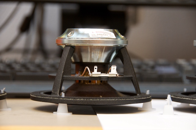
The Scanspeak Illuminator uses the underhung design, which is is not hard to figure out just by looking at the photos of it in Figures 12 and 13.
Wrapping up
The stiffness and Bl curves of the Illuminator midrange and the resulting low distortion are just one aspect of the driver that contributed to its choice for the Beolab 90. As I said at the start of the article, there are many, many factors that have to be considered when choosing a driver for a loudspeaker. It is also important to remember that a driver that is a good choice for one loudspeaker does not necessarily mean that it’s a good choice for another loudspeaker. A gearbox that’s perfect for a racing motorcycle is not necessarily going to work well on an 18-wheeler truck. A racing bicycle can go fast partly due to its tires – however, if you put the same tires on a Ferrari, you won’t get very far… Every individual component of any loudspeaker has to be chosen with all of the other components in mind to build an optimal system.
Jeff says:
An excellent primer on driver selection criteria! I remember, back in the 90s, being fascinated by a presentation at an ALMA meeting of a paper on signal induced driver self noise, that is the noise the physical material of the driver makes in response to the signal, modulating the signal and also sub bands as a result of the sound of the drivers materials as it goes thru breakup modes and such. Was interesting in that it gave a reason, backed up with some great plots/measurements, of how the more rigid drivers often had significant issues with ringing and self noise that showed up as not far below the signal. Think of how say a piece of cloth sounds when you flex it vs. how a piece of more rigid plastic sounds.
Did this ever go anywhere? Is it something considered these days or was it too narrowly focused and not generally accepted? I found it fascinating as I said, it seemed to offer an explanation for some of what I heard with rigid drivers.
Teddy says:
This has been very helpful! You go into detail in a way that makes a clear picture.
Like the above comment, I too am interested in your knowledge of cone material effects!
Thank you Geoff
Dan the Man says:
As far as I’m concerned if you want the most natural uncolored and detailed speakers, there is no substitute for plasma tweeters and electrostatic speakers which are push and pulled and have no mass or thousandths of the mass to move with very linear extended frequency response no cone can match, if done right (not on the market) they can play very loud (125db @20 feet) with far less distortion than any cone driver, everything else is inferior, cones don’t do it.
Dan the Man says:
The patented JBL dual differential drive speaker solve the same problems even better for cone type speakers and are push and pulled.
Bernd says:
Can one really tell me why so many, i think the most, manufacturers still use spiders for thei drivers. Never seen one for a tweeter but for almost every woofer. What happens to the soundwaves that are produced by the spider, when they hit the back of the diaphragm? I guess drivers with lowest manufacturing tollerance could be build without the spiders.
Thanx in advance for he answer
Bernd
geoff says:
Hi Bernd,
Sorry it has taken so long to address your question. I needed to talk to a couple of people about this before putting something in writing.
You’re correct – there is a pressure wave that is produced by the spider that radiates (more or less) as a dipole, with one lobe aimed at the back of the diaphragm. This effect is well-known by driver designers (at least, the ones I talked to…). In some extreme cases, the effect of this wave is measurable acoustically in front of the driver. However, in almost all cases, the effect is extremely small – one might say negligible – due to a number of issues including the fact that the spider is typically made of an open mesh and that the motor of the driver is easily able to overcome the effects.
There are, however, other issues that are worth worrying about that make the spider’s pressure wave irrelevant. One in particular that is commonly known is the potential problem of the creation of a Helmholtz resonator caused by the depth of the loudspeaker cabinet restricting airflow in and out of the driver’s basket. This can cause a resonance that is easily audible (and therefore measurable). One solution to this is to chamfer, bevel, or round the interior of the cabinet around the opening for the driver. This, however, weakens the baffle and can result in a shortened lifespan or panel resonances – or both. One added advantage to doing this, however, is that it will reduce the amount of turbulence caused when the air flows around the cabinet opening as the driver moves (this problem decreases exponentially with frequency, assuming a constant SPL). Whether this turbulence is audible (or measurable) is dependent on many, many things.
Thanks for asking the question – it’s caused me to learn some stuff about drivers that I wasn’t aware of. It also makes me think that it could make for an interesting posting on the site – particularly since some photos and drawings would help explain the previous paragraph…
Cheers
-geoff