Back in Part II of what is turning out to be a series of postings on this topic, I wrote
If this were a digital system instead of an analogue one, we would be describing this as ‘signal-dependent jitter’, since it is a time modulation that is dependent on the slope of the signal. So, when someone complains about jitter as being one of the problems with digital audio, you can remind them that vinyl also suffers from the same basic problem…
As I was walking the dog on another night, I got to thinking whether it would be possible to compare this time distortion to the jitter specifications of a digital audio device. In other words, is it possible to use the same numbers to express both time distortions? That question led me here…
Remember that the effect we’re talking about is caused by the fact that the point of contact between the playback needle and the surface of the vinyl is moving, depending on the radius of the needle’s curvature and the slope of the groove wall modulation. Unless you buy a contact line needle, then you’ll see that the radius of its curvature is specified in µm – typically something between about 5 µm and 15 µm, depending on the pickup.
Now let’s do some math. The information and equations for these calculations can be found here.
We’ll start with a record that is spinning at 33 1/3 RPM. This means that it makes 0.556 revolutions per second.
The Groove Speed relative to the needle is dependent on the rotation speed and the radius – the distance from the centre of the record to the position of the needle. On a 12″ LP, the groove speed at the outside groove where the record starts is 509.8 mm/sec. At the inside groove at the end of the record, it’s 210.6 mm/sec.
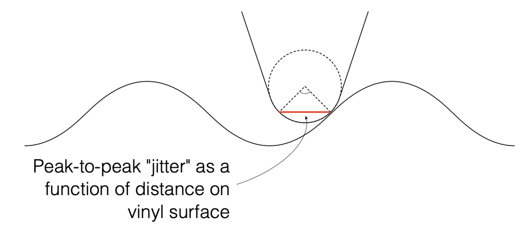
Let’s assume that the angular rotation of the contact point (shown in Figure 1) is 90º. This is not based on any sense of scale – I just picked a nice number.

We can convert that angular shift into a shift in distance on the surface of the vinyl by finding the distance between the two points on the surface, as shown below in Figure 2. Since you might want to choose an angular rotation that is not 90º, you can do this with the following equation:
2 * sin(AngularRotation / 2) * radius
So, for example, for a needle with a radius of 10 µm and a total angular rotation of 90º, the distance will be:
2 * sin(90/2) * 10 = 14.1 µm

We can then convert the “jitter” as a distance to a jitter in time by dividing it by the distance travelled by the needle each second – the groove speed in µm per second. Since that groove speed is dependent on where the needle is on the record, we’ll calculate it as best-case and a worst-case values: at the outside and the inside of the record.
Jitter Distance / Groove Speed = Jitter in time
For example, at the inside of the record where the jitter is worst (because the wavelength is shortest and therefore the maximum slope is highest), the groove speed is about 210.6 mm/sec or 210600 µm/sec.
Then the question is “what kind of jitter distance should we really expect?”

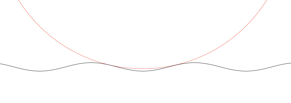
Looking at Figure 3 which shows a scale drawing of a 15 µm radius needle on a 1 kHz tone with a modulation velocity of 50 mm/s (peak) on the inside groove of a record, we can see that the angular rotation at the highest (negative) slope is about 13.4º. This makes the total range about 27º, and therefore the jitter distance is about 7.0 µm.
If we have a 27º angular rotation on a 15 µm radius needle, then the jitter will be
7.0 / 210600 = 0.0000332 or 33.2 µsec peak-to-peak
Of course, as the radius of the needle decreases, the angular rotation also decreases, and therefore the amount of “jitter” drops. When the radius = 0, then the jitter = 0.
It’s also important to note that the jitter will be less at the outside groove of the record, since the wavelength is longer, and therefore the slope of the groove is lower, which also reduces the angular rotation of the contact point.
Since the groove on records are typically equalised to ensure that you have a (roughly) constant velocity above 1 kHz and a constant amplitude below, then this means that the maximum slope of the signal and therefore the range of angular rotation of the contact point will be (roughly) the same from 1 kHz to 20 kHz. As the frequency of the signal descended from 1 kHz and downwards, the amplitude remains (roughly) the same, so the velocity decreases, and therefore the range of the angular rotation of the contact point does as well.
In other words, the amount of jitter is 0 at 0 Hz, and increases with frequency until about 1 kHz, then it remains the same up to 20 kHz.
As one final thing: as I was drawing Figure 3, I also did a scale drawing of a 20 kHz signal with the same 50 mm/s modulation velocity and the same 15 µm radius needle. It’s shown in Figure 4.

As you can see there, the needle’s 15 µm radius means that it can’t drop into the trough of the signal. So, that needle is far too big to play a CD-4 quad record (which can go all the way up to 45 kHz).