I spent some time this week helping to track down the source of an error in a digital audio signal flow chain, and we wound up having a discussion that I thought might be worth repeating here.
Let’s start at the very beginning.
Let’s take an analogue audio signal and convert it to a Linear Pulse Code Modulation (LPCM) representation in the dumbest possible way.
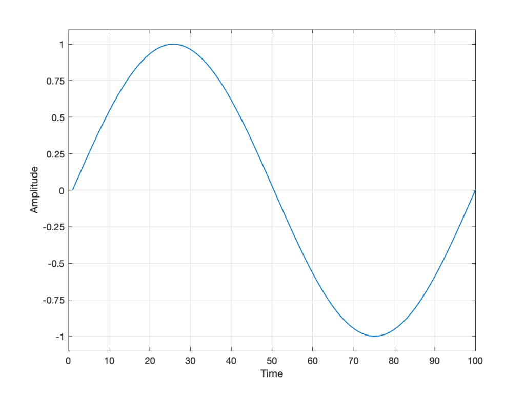
In order to save this signal as a string of numerical values, we have to first accept the fact that we don’t have an infinite number of numbers to use. So, we have to round off the signal to the nearest usable value or “quantisation value”. This process of rounding the value is called “quantisation”.
Let’s say for now that our available quantisation values are the ones shown on the grid. If we then take our original sine wave and round it to those values, we get the result shown below.
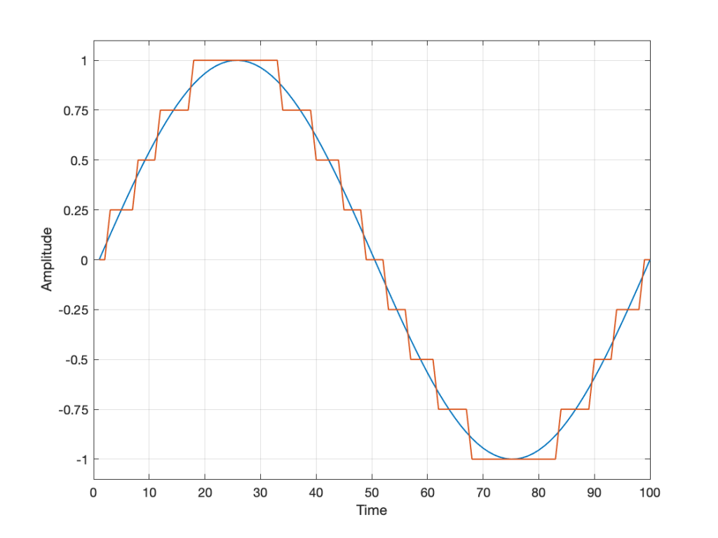
Of course, I’m leaving out a lot of important details here like anti-aliasing filtering and dither (I said that we were going to be dumb…) but those things don’t matter for this discussion.
So far so good. However, we have to be a bit more specific: an LPCM system encodes the values using binary representations of the values. So, a quantisation value of “0.25”, as shown above isn’t helpful. So, let’s make a “baby” LPCM system with only 3 bits (meaning that we have three Binary digITs available to represent our values).
To start, let’s count using a 3-bit system:
| Binary Value | 4s place | 2s place | 1s place | Decimal Value | ||
| 000 | = | 0 x 4 + | 0 x 2 + | 0 x 1 | = | 0 |
| 001 | = | 0 x 4 + | 0 x 2 + | 1 x 1 | = | 1 |
| 010 | = | 0 x 4 + | 1 x 2 + | 0 x 1 | = | 2 |
| 011 | = | 0 x 4 + | 1 x 2 + | 1 x 1 | = | 3 |
| 100 | = | 1 x 4 + | 0 x 2 + | 0 x 1 | = | 4 |
| 101 | = | 1 x 4 + | 0 x 2 + | 1 x 1 | = | 5 |
| 110 | = | 1 x 4 + | 1 x 2 + | 0 x 1 | = | 6 |
| 111 | = | 1 x 4 + | 1 x 2 + | 1 x 1 | = | 7 |
and that’s as far as we can go before needing 4 bits. However, for now, that’s enough.
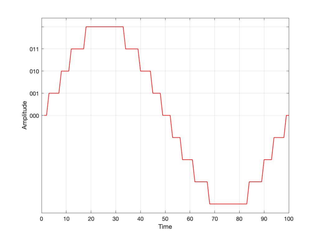
Take a look at our signal. It ranges from -1 to 1 and 0 is in the middle. So, if we say that the “0” in our original signal is encoded as “000” in our 3-bit system, then we just count upwards from there as follows:
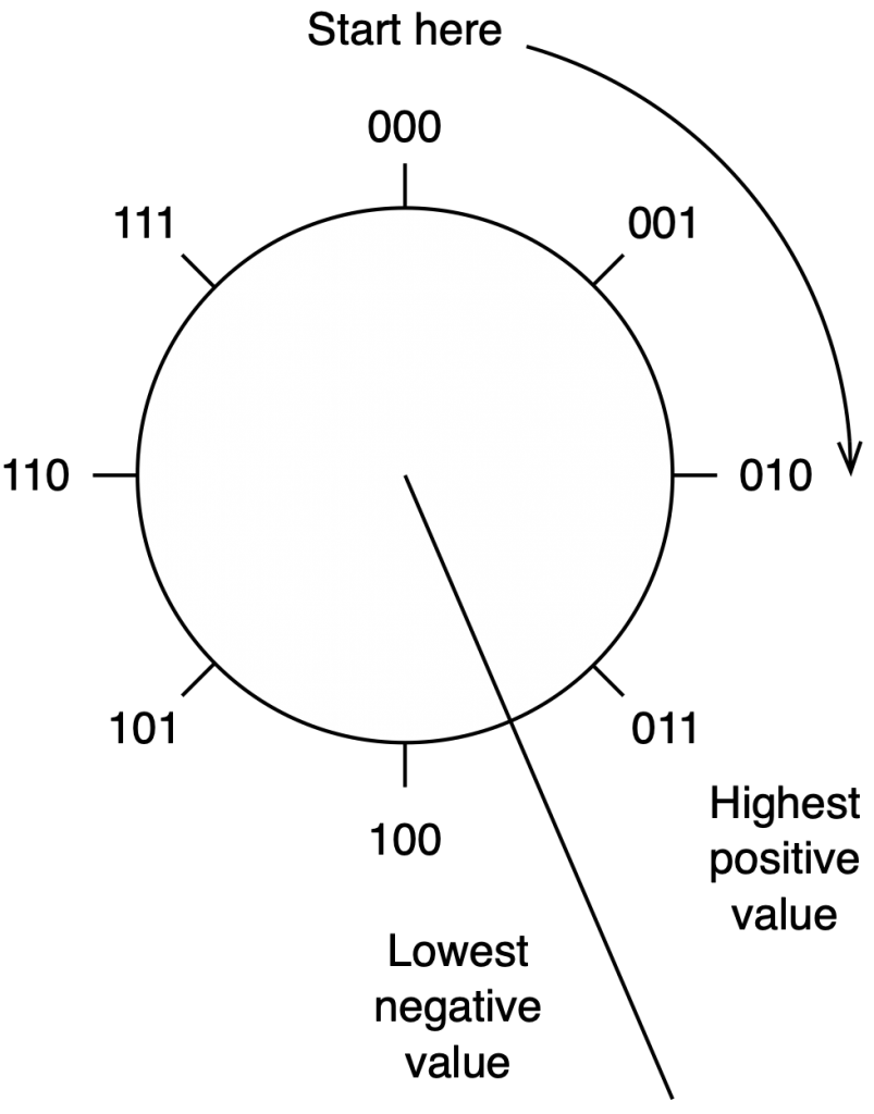
Now what? Well, let’s look at this a little differently. If we were to divide a circle into the same number of quantisation values, make the “12:00” position = 000, and count clockwise, it would look like this:

The question now is “how do we number the negative values?” but the answer is already in the circle shown above… If I make it a little more obvious, then the answer is shown below.
If we use the convention shown above, and represent that on the graph of our audio signal, then it looks like this:
One nice thing about this way of doing things is that you just need to look at the first digit in the binary word to know whether the value is positive or negative. A 0 means it’s positive, and a 1 means it’s negative.
However, there are two issues here that we need to sort out… The first is that, since we have an even number of values, but an odd number of quantisation steps (4 above zero, 4 below zero, and zero = 9 steps) then we had to do something asymmetrical. As you can see in the plot above, there are no numbers assigned to the top quantisation value, which actually means that it doesn’t exist.
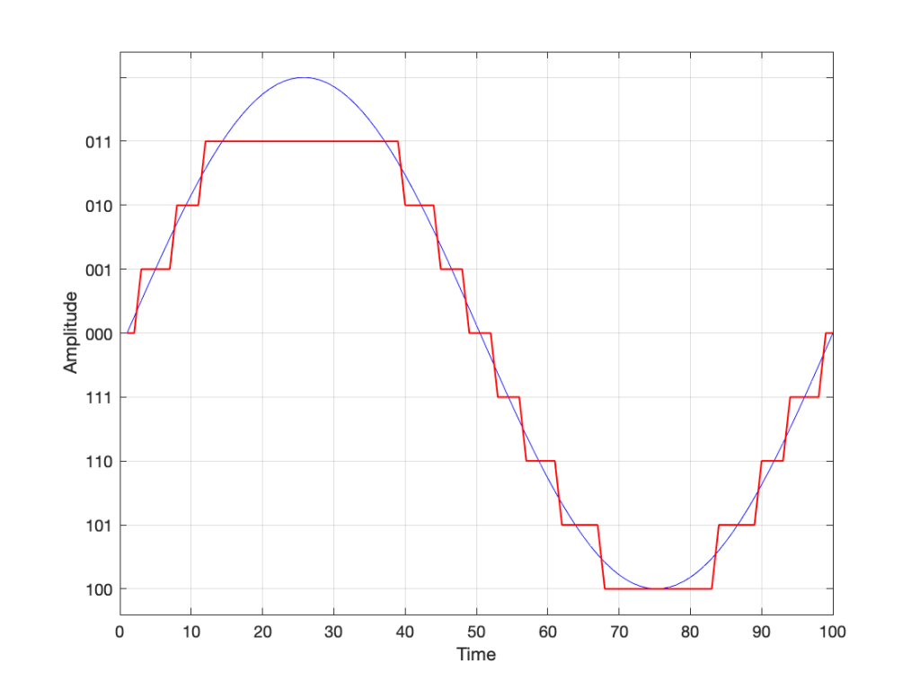
So, if we’re still being dumb, then the result of our quantisation will either look like this:
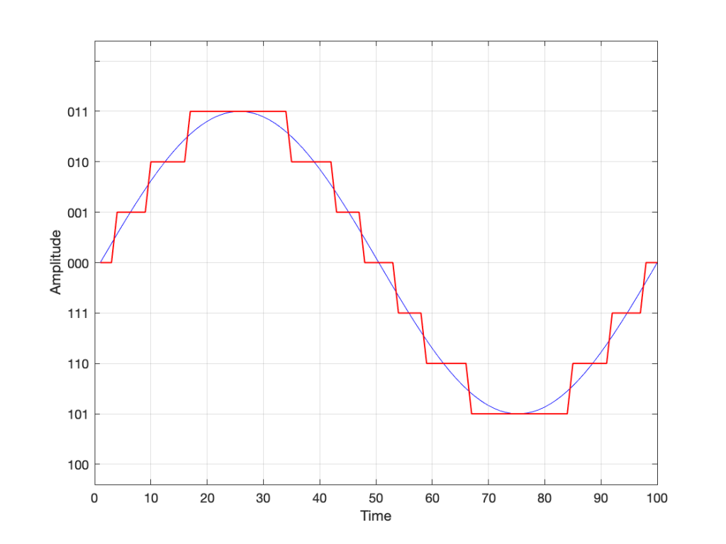
or this:
Wrapping up…
But what happens when you make two mistakes simultaneously? Let’s go back and look at an earlier plot.

Let’s say that you’re writing some DSP code, and you forget about the asymmetry problem, so you scale things so they’ll TRY to look like the plot above.
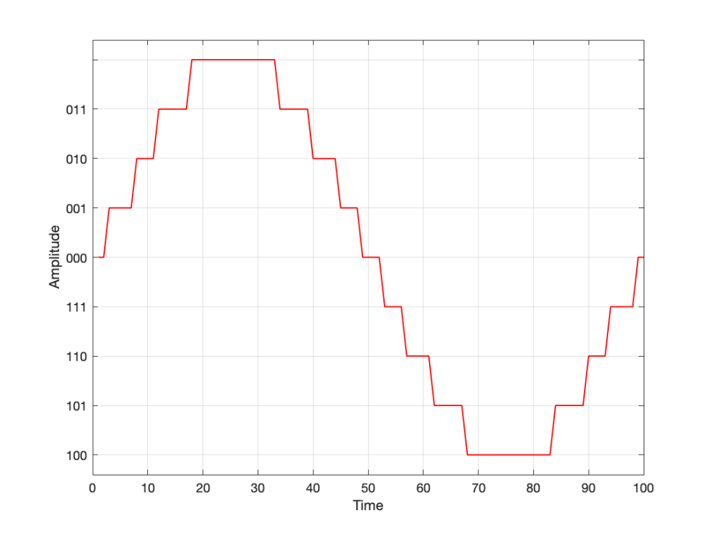
However, as we already know, that top quantisation value doesn’t exist – but the code will try to put something there. If you’ve forgotten about this, then the system will THINK that you want this:
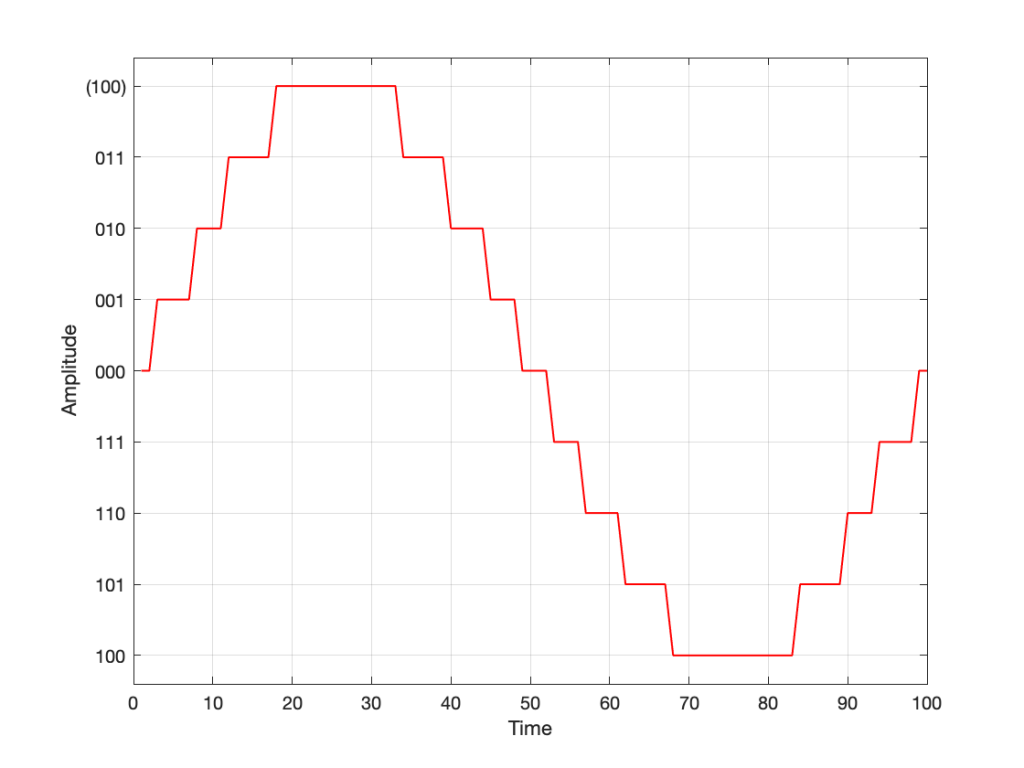
As you can see there, your code (because you’ve forgotten to write an IF-THEN statement) will think that the top-most positive quantisation value is just the number after 011, which is 100. However, that value means something totally different… So, the result coming out will ACTUALLY look like this:
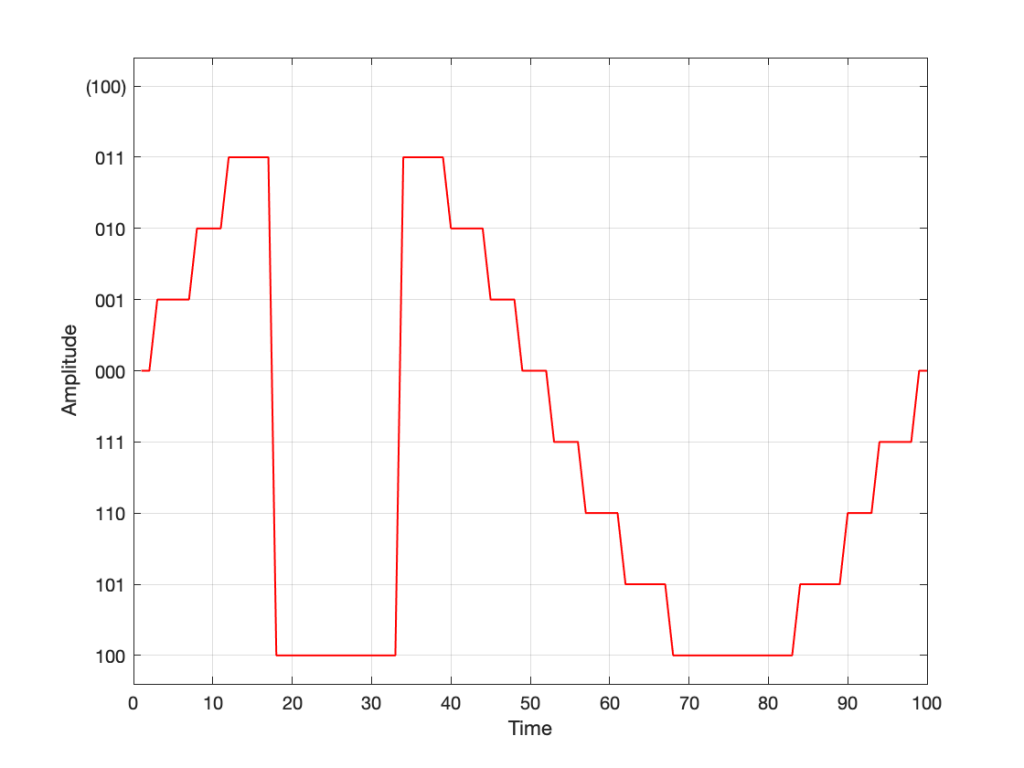
As you can see there, the signal is very different from what we think it should be.
This error is called a “wrapping” error, because the signal is “wrapped” too far around the circle shown in Figure 5, shown above. It sounds very bad – much worse than “normal” clipping (as shown in Figure 7) because of that huge nearly-instantaneous transition from maximum positive to maximum negative and back.
Of course, the wrapping can also happen in the opposite direction; a negatively-clipped signal can wrap around and show up at the top of the positive values. The reason is the same because the values are trying to go around the same circle.
As I said: this is actually the result of two problems that both have to occur in the same system:
- The signal has to be trying to get to a level that is beyond the limits of the quantisation values
- Someone forgot to write a line of code that makes sure that, when that happens, the signal is “just” clipped and not wrapped.
So, if the second of these issues is sitting there, unresolved, but the signal never exceeds the limits, then you’ll never have a problem. However, I will never need the airbags in my car, unless I have an accident. So, it’s best to remember to look after that second issue… just in case.
P.S.
This method of encoding the quantisation values is called the “Two’s Complement” method. If you want to know more about it, read this.