#2 in a series of articles about wander and jitter
In the previous posting, I talked a little about what jitter and wander are, and one of the many things that can cause it. The short summary of that posting is:
Jitter and wander are the terms given to a varying error in the clock that determines when an audio sample should (or did) occur.
Note the emphasis on the word “varying”. If the clock is consistently late by a fixed amount of time, then you don’t have jitter or wander. The clock has to be speeding up and slowing down.
One of the ways you can categorise jitter is by separating the problem into two dimensions – phase (or time) and amplitude.
Let’s say that
- you have a “square wave” that carries your encoded digital audio signal coming into your device, AND
- you are creating a clock “tick” based on the time of the transition between the high and low voltages AND
- you are detecting this transition by looking at what time the voltage value crossed the threshold, which is half-way between your high and low voltages
IF there is a variation ONLY in the time that the voltage crossed the threshold – not in the high and low voltage values themselves, then you have what is called phase jitter. This is probably easier to understand if you look at Figure 1, below.
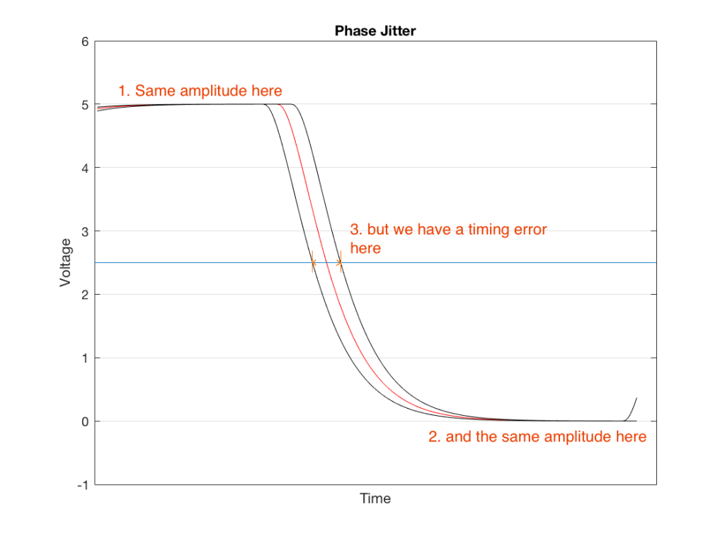
There are three curves in Figure 1. The red curve is the “good” one – it shows the voltage changing from high to low (in this case, 5 V and 0 V), at exactly the right time.
The black curve to the left of this shows an example of a transition that happens too early for some unknown reason. Although that black line also changes from 5 V to 0 V, it does it too early, giving us a timing error when we look at the moment it crosses the threshold (the line at 2.5 V).
The black curve to the right shows an example of a transition that happens too late for some unknown reason. Although that black line also changes from 5 V to 0 V, it does it too late, giving us a timing error when we look at the moment it crosses the threshold (the line at 2.5 V).
As I said above, jitter and wander are the result of a variation in the time that we cross that threshold. So, we will talk about peak-to-peak jitter measurements – a measurement of the amount of time between the earliest detected transition to the latest one. This allows us to not worry so much about measuring a single transition’s error relative to when it should have happened (which would be difficult to do). It’s much easier to just look at the incoming signal over time, and measure the difference in time between the earliest and the latest – the total “width” of the error in time.
The second classification of jitter is sort of a “side effect” of a different problem. If we take the square wave and we change its amplitude – so we have an error in its voltage level – then a by-product of this is a change in the time the transition crosses the threshold. This is called amplitude jitter and is shown in Figure 2.
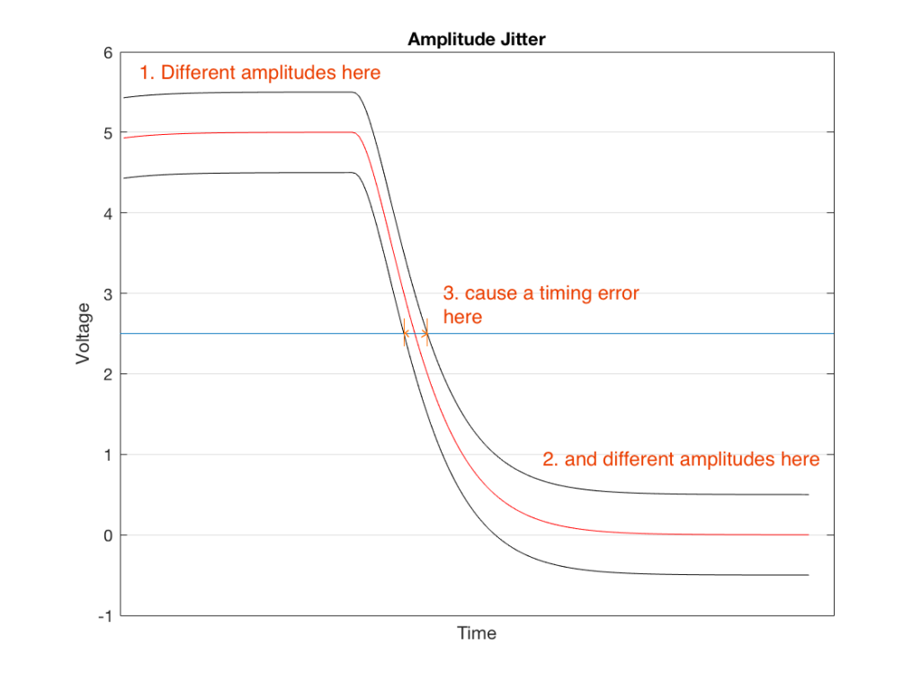
Notice here that the reason the error occurs in time is that we have an error in level. The value of the threshold (the horizontal line at 2.5 V) is based on the assumption that our high and low voltages are 5 V and 0 V. If we have an amplitude error (say, in the case of the upper curve in this plot, 5.5 V and 0.5 V) then the threshold (still at 2.5 V) is too low – so the time the voltage crosses that line will be late.
So, if you have a modulation (a change) in the amplitude (the voltage level) of the signal, then you will also get a modulation in the timing information, resulting in jitter and wander.
Again, this error in time is probably most easily measured as a peak-to-peak jitter value.
Wrapping up
If you’re a system developer or if you’re trying to improve your system, you need to know whether you have phase jitter or amplitude jitter in order to start tracking down the root cause of it so that you can fix it. (If your car doesn’t start and you want to fix it, it’s good to find out whether you are out of fuel or if you have a dead battery… These are two different problems…)
However, if you’re just interested in evaluating the performance of a system, one thing you can do is simply to ask “how much jitter do I have?” (If your car doesn’t start, you’re not going to get to work on time… Whether it’s your battery or your fuel is irrelevant.) You measure this, and then you can make a decision about whether you need to worry about it – whether it will have an effect on your audio quality (which is a question that not determined so much by the amount of jitter that you have, but where it is in your system, and how the “downstream” devices can deal with it).