#91.1 in a series of articles about the technology behind Bang & Olufsen
Without connecting external loudspeakers, Bang & Olufsen’s Beosound Theatre has a total of 11 independent outputs, each of which can be assigned any Speaker Role (or input channel). Four of these are called “virtual” loudspeakers – but what does this mean? There’s a brief explanation of this concept in the Technical Sound Guide for the Theatre (you’ll find the link at the bottom of this page), which I’ve duplicated in a previous posting. However, let’s dig into this concept a little more deeply.
To begin, let’s put a “perfect” loudspeaker in a free field. This means that it’s in a space that has no surfaces to reflect the sound – so it’s an acoustic field where the sound wave is free to travel outwards forever without hitting anything (or at least appear as this is the case). We’ll also put a “perfect” microphone in the same space.

We then send an impulse; a very short, very loud “click” to the loudspeaker. (Actually a perfect impulse is infinitely short and infinitely loud, but this is not only inadvisable but impossible, and probably illegal.)
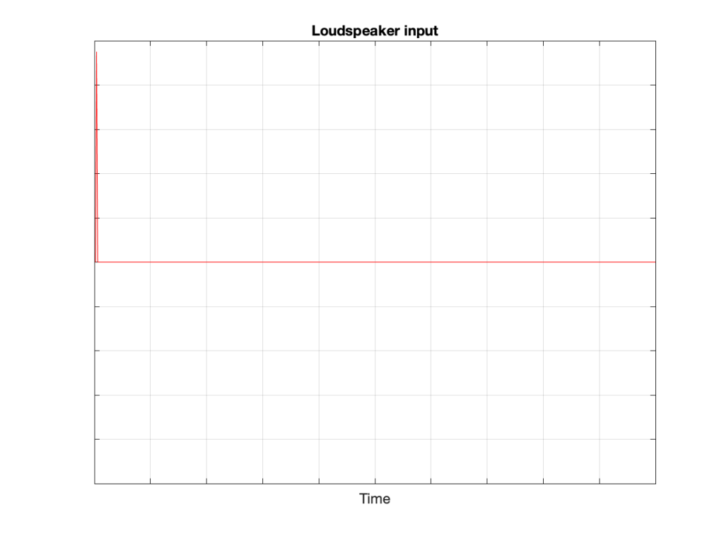
That sound radiates outwards through the free field and reaches the microphone which converts the acoustic signal back to an electrical one so we can look at it.
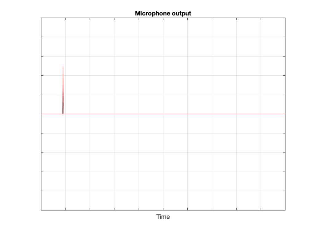
There are three things to notice when you compare Figure 3 to Figure 2:
- The signal’s level is lower. This is because the microphone is some distance from the loudspeaker.
- The signal is later. This is because the microphone is some distance from the loudspeaker and sound waves travel pretty slowly.
- The general shape of the signals are identical. This is because I said that the loudspeaker and the microphone were both “perfect” and we’re in a space that is completely free of reflections.
What happens if we take away the microphone and put you in the same place instead?

If we now send the same click to the loudspeaker and look at the “outputs” of your two eardrums (the signals that are sent to your brain), these will look something like this:
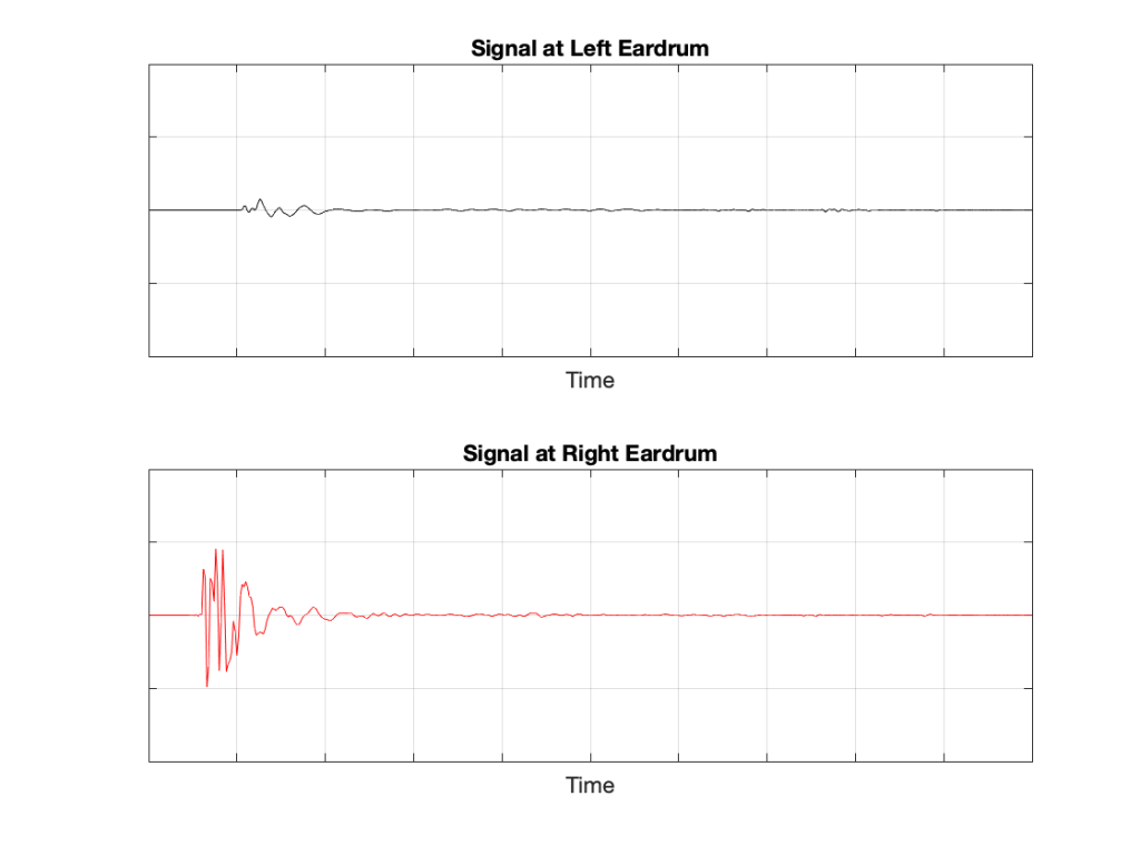
These two signals are obviously very different from the one that the microphone “hears” which should not be a surprise: ears aren’t microphones. However, there are some specific things of which we should take note:
- The output of the left eardrum is lower than that of the right eardrum. This is largely because of an effect called “head shadowing” which is exactly what it sounds like. The sound is quieter in your left ear because your head is in the way.
- The signal at the right eardrum is earlier than at the left eardrum. This is because the left eardrum is not only farther away, but the sound has to go around your head to get there.
- The signal at the right eardrum is earlier than the output of the microphone output (in Figure 3) because it’s closer to the loudspeaker. (I put the microphone at the location of the centre of the simulated head.) Similarly the left ear output is later because it’s farther away.
- The signal at the right eardrum is full of spikes. This is mostly caused by reflections off the pinna (the flappy thing on the side of your head that you call your “ear”) that arrive at slightly different times, and all add together to make a mess.
- The signal at the left eardrum is “smoother”. This is because the head itself acts as a filter reducing the levels of the high frequency content, which tends to make things less “spiky”.
- Both signals last longer in time. This is the effect of the ear canal (the “hole” in the side of your head that you should NOT stick a pencil in) resonating like a little organ pipe.
The difference between the signals in Figures 2 and 4 is a measurement of the effect that your head (including your shoulders, ears/pinnae) has on the transfer of the sound from the loudspeaker to your eardrums. Consequently, we geeks call it a “head-related transfer function” or HRTF. I’ve plotted this HRTF as a measurement of an impulse in time – but I could have converted it to a frequency response instead (which would include the changes in magnitude and phase for different frequencies).
Here’s the cool thing: If I put a pair of headphones on you and played those two signals in Figure 5 to your two ears, you might be able to convince yourself that you hear the click coming from the same place as where that loudspeaker is located.
Although this sounds magical, don’t get too excited right away. Unfortunately, as with most things in life, reality tends to get in the way for a number of reasons:
- Your head and ears aren’t the same shape as anyone else’s. Your brain has lived with your head and your ears for a long time, and it’s learned to correlate your HRTFs with the locations of sound sources. If I suddenly feed you a signal that uses my HRTFs, then this trick may or may not work, depending on how similar we are. This is just like borrowing someone else’s glasses. If you have roughly the same prescription, then you can see. However, if the prescriptions are very different, you’ll get a headache very quickly.
- In reality, you’re always moving. So, even if the sound source is not moving, the specific details of the HRTFs are always changing (because the relative positions and angles to your ears are changing) but my system doesn’t know about this – so I’m simulating a system where the loudspeaker moves around you as you rotate your head. Since this never happens in real life, it tends to break the simulation.
- The stuff I showed above doesn’t include reflections, which is how you determine distance to sources. If I wanted to include reflections, each reflection would have to have its own HRTF processing, depending on its angle relative to your head.
However, hypothetically, this can work, and lots of people have tried. The easiest way to do this is to not bother measuring anything. You just take a “dummy head” -a thing that is the same size as an average human head (maybe with an average torso) and average pinnae* – but with microphones where the eardrums are – and you plunk it down in a seat in a concert hall and record the outputs of the two “ears”. You then listen to this over earphones (we don’t use headphones because we want to remove your pinnae from the equation) and you get a “you are there” experience (assuming that the dummy head’s dimensions and shape are about the same as yours). This is what’s known as a binaural recording because it’s a recording that’s done with two ears (instead of two or more “simple” microphones).
If you want to experience this for yourself, plug a pair of headphones into your computer and do a search for the “Virtual Barber Shop” video. However, if you find that it doesn’t work for you, don’t be upset. It just means that you’re different: just like everyone else.* Typically, recordings like this have a strange effect of things sounding very close in the front, and farther away as sources go to the sides. (Personally, I typically don’t hear anything in the front. All of the sources sound like they’re sitting on the back of my neck and shoulders. This might be because I have a fat head (yes, yes… I know…) and small pinnae (yes, yes…. I know…) – or it might indicate some inherent paranoia of which I am not conscious.)
* Of course, depressingly typically, it goes without saying that the sizes and shapes of commercially-available dummy heads are based on averages of measurements of men only. Neither women nor children are interested in binaural recordings or have any relevance to such things, apparently…