It should not come as a surprise that, when we talk about how a vinyl record works, we can start by looking at the movement of the needle in the groove. If we simplify that connection a little (by reducing the audio signal to one channel, but we’ll come back to that point later), then we can think of this as a needle, sitting on a surface. The needle is at the end of an arm that we call the “cantilever” (because it is fixed on one end and it can move up and down on the other end where the needle is attached) and that cantilever is attached somehow to the tonearm using a springy material of some kind (like rubber, for example).
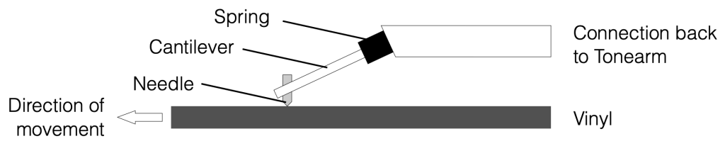
The simple diagram above shows that arrangement. Of course, I’ve left out a bunch of things, and nothing is to scale, but those details are not important right now.
I’ll make the “spring” in this diagram out of flexible rubber that has some “springiness” or “compliance”. The more compliant the spring, the easier it is to flex. So a stiff spring in not very compliant. (This concept is very important to understand as we go on.)
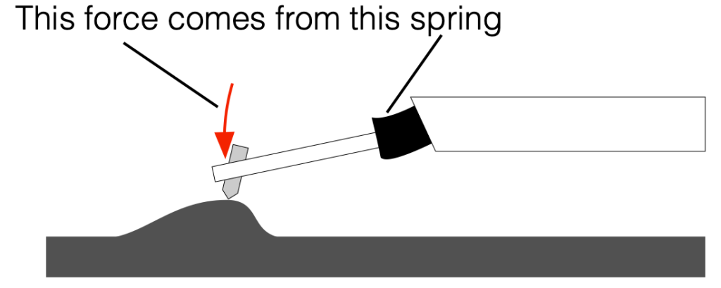
The audio signal is “encoded” into the surface of the vinyl using bumps and dips that cause the needle to move up and down. I’ve shown this in the simple diagram below.

Notice in that diagram that the needle is in contact with the surface of the vinyl, but the part of the system that connects back to the tonearm has not lifted. This is because the connection between the cantilever and the tonearm assembly is compliant enough to let the cantilever move upwards (or downwards) without moving the rest of the system.
Think of this like driving over a very small bump in the road in your car. The compliance of the tires and the shock absorbers will result in the tire riding over the bump, but the car doesn’t jump as a result.
Remember that the bump in the surface of the vinyl is only passing by, so the needle isn’t raised for long. As a result part of the reason the tonearm doesn’t move upwards (and your car doesn’t jump) is partly because it’s heavy. Its mass results in an inertia that “wants” to stop it from moving up and down. (The other factor that’s involved here is an adjustment in the tonearm called the “tracking force” which is a measurement of how much the tonearm is pushing downwards on the needle.)
Consequently, when that bump comes along, the needle rides on top of it, and the force that is pushing it downwards comes mostly from the “spring” at the other end of the cantilever, as shown below.
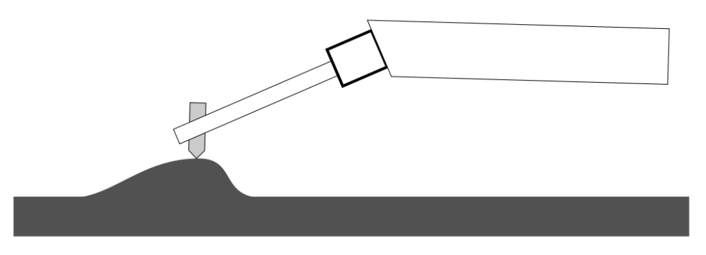
If the spring had no compliance (in other words, if it weren’t a spring, and the cantilever were just connected directly to the tonearm) and if the cantilever and needle were strong enough to take the force, then the entire tonearm assembly would jump up and down instead, as shown below. (Imagine riding in a horse-drawn buggy with wooden wheels with steel rims, and no springs on the axles. You’d feel every single rock on the road…)
The tonearm is resting on two points: one is the tip of the needle and the other is at the other end at the pivot point where it also rotates horizontally as you play the album. If we were really dumb turntable designers, then half of the mass of the tonearm would be resting on the needle (and the other half would be resting on the pivot). This would be bad, since your records would wear out very fast. So, a tonearm has some kind of adjustment on it that reduces the amount of weight on the needle. The simplest way to do this is to put a counterweight on the opposite side of the pivot so it’s more like a see-saw at the playground. As you move the counterweight away from the pickup, the downwards force at the needle gets smaller. In fact, you can probably adjust the counterweight so far that the needle-end of the tonearm is lighter, and it is stuck up in the air…
We adjust the amount of downwards force at the needle (called the “tracking force”) to result in a value that is in balance with the compliance of the connection to the cantilever. If the tracking force is too high (or the compliance is too high for the tracking force) then the tonearm will sink like I’ve shown below.

There are lots of things wrong with this. The first is that the needle isn’t at the correct angle to the surface of the vinyl, so it’s not going to move correctly. The second is that the cantilever is at the wrong angle, so it’s not going to move upwards with the same behaviour as it moves downwards, which results in an asymmetrical distortion of the signal. But possibly the most obvious problem is that there’s just too much downwards pressure on the vinyl, so your records will wear out faster.
So, there is a balance between the tracking force and the compliance. That balance ensures that you always have contact between the tip of the needle and the surface of the vinyl as the bumps and dips go by.
Digging into the details
One of the things I do regularly is to measure the magnitude response of a turntable from the surface of the vinyl to the electrical output of the RIAA preamplifier. In order to do this, I play two tracks on a special test record (Brüel & Kjær QR 2010) which has the following audio signals:
- Track 1
- 2 seconds of 1 kHz sinusoidal wave, L&R channels (3.16 cm/sec lateral velocity)
- 20 Hz to 45 kHz sinusoidal tone, log sweep, 5 sec per decade, Left channel
- Track 2
- 2 seconds of 1 kHz sinusoidal wave, L&R channels (3.16 cm/sec lateral velocity)
- 20 Hz to 45 kHz sinusoidal tone, log sweep, 5 sec per decade, Right channel
Sometimes (but very rarely), I notice that the needle will skip (or jump) at the transition between the 1 kHz tone and the start of the sine sweep. If this happens, for track 1, the needle will skip forwards into the sweep.
When this happened the first time I thought “Ah hah! The tracking force isn’t high enough, so the needle is being thrown out of the groove. I just need to adjust it.” But after checking the tracking force with my meter (a very small, very precise and accurate scale), I found out that this was not the problem.
Of course, I could make the problem go away by increasing the tracking force, but then it was too high, and my records (and the needle tip) will wear down faster. This would be covering up the symptom, but not correcting the actual problem.
So, what is the problem? It’s that the compliance of the pickup is too low due to an error in the manufacturing process or the fact that it’s just old and the rubber has stiffened over time. In other words it looks more like the system shown in Figure 4, above.
Let’s take a system where the pickup compliance is too low (so the spring is too stiff), so the tonearm can be tossed up off the vinyl surface. We then combine that with the knowledge of how the needle sits in the groove on the vinyl and which channel is on which side of that groove (which I’ve shown below in Figure 6).
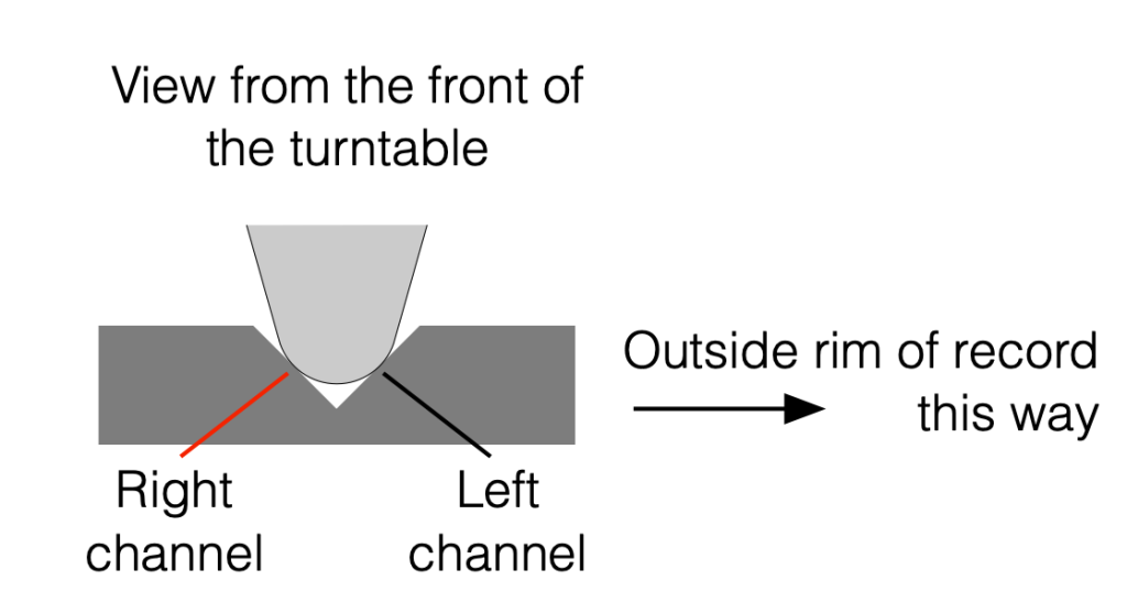
Now we can see that, if there’s a bump in the Left channel, it will push the needle on a 45º angle upwards, and if the tracking force and compliance aren’t working together as they should, then the entire tonearm can be pushed hard enough to cause the needle to lift off the surface of the vinyl, heading in towards the centre of the record (towards the left in Figure 6).
What does the signal actually look like?
Let’s go back and look at a recording of that transition between the 1 kHz tone and the start of the 20 Hz sweep, using a pickup that is behaving properly.
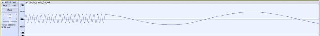
The figure above is a screenshot from Audacity that shows the “raw” signal that I recorded at the input of my sound card which is connected to the output of the RIAA preamplifier. I’ve zoomed in to the moment when the track transitions from the 1 kHz tone to the 20 Hz tone at the start of the sweep.
Let’s now use this to go backwards and try to figure out what the surface of the vinyl looks like. I’ll start by re-creating a “perfect” version of that signal in Matlab by joining a 1 kHz cosine wave to a 20 Hz cosine wave.
You might notice that I’ve changed the value a little. I’m simulating one channel of a tone that has a level of at 5 cm/sec, RMS lateral velocity for two channels, instead of the 3.16 cm/sec from the B&K record. But this doesn’t really matter too much – I’ve just done it to make the numbers look nice and be a little easier to talk about.
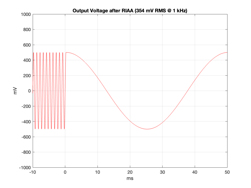
I’m simulating a system that has a total gain set so that a modulation velocity of 3.54 cm/sec in one channel will produce 354 mV RMS (500 mV peak) at the output of the RIAA at 1 kHz.
Since the lateral velocity of a two-channel tone is 5 cm/sec, then the velocity of one channel will be 1/sqrt(2) of that value because the groove wall is 45º away from the lateral axis and cos(45º) = 1/sqrt(2).
If we take the signal in Figure 8 and filter it with a RIAA pre-emphasis filter (sometime called an “anti-RIAA” or an “inverse RIAA”) and drop the level by 40 dB (a typical gain for a RIAA preamp), then the signal looks like the plot in Figure 9.
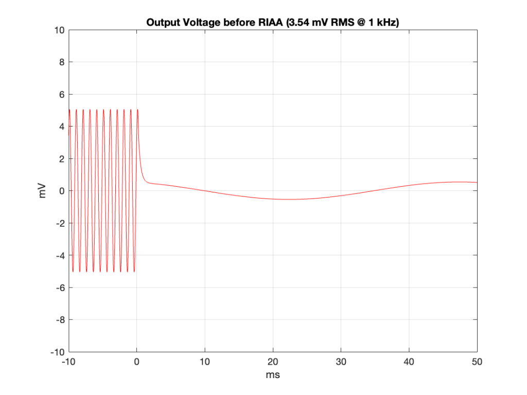
As you can see there, the signal much lower in level overall (because of the -40 dB gain) and the 20 Hz tone is much lower in level than the 1 kHz tone (because of the pre-emphasis filter).
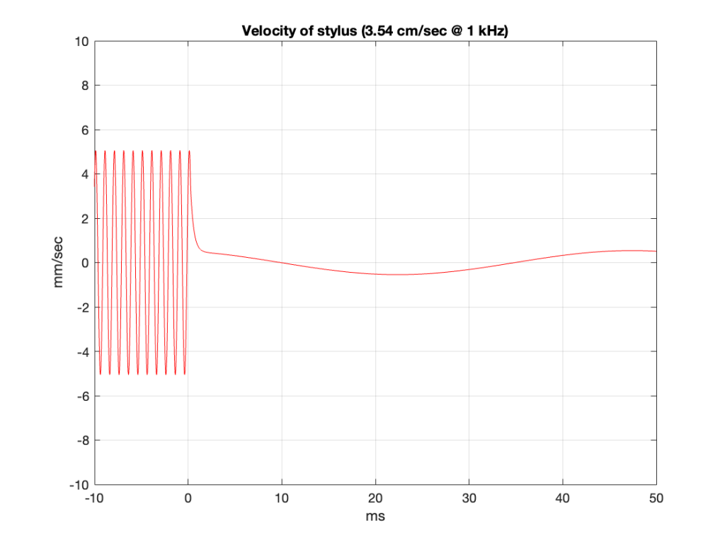
The output of the pickup is a current that is proportional to the velocity of the needle. So, we can move farther backwards in the chain and plot the velocity of the needle over time, shown in Figure 10. As you can see, the shape of this plot looks identical to the one in Figure 9. This is because I’m assuming that the current output of the pickup is in phase with the voltage at the input of the RIAA. (This is a safe assumption for the two frequencies we’re looking at here. If you want to pick a fight with me about this, drop by and do it in person. But you’re buying the beer…)
Now comes a jump… the velocity of the needle can be calculated by finding the derivative of the displacement over time, which means that the displacement can be found by integrating the velocity.
If you don’t like calculus, then you can think of it this way: In the old days, if you drove from Struer to Copenhagen, you had to take a ferry to get from the island of Fyn to the island of Zealand. Every once in a while, there would be a policeperson, walking around the parking lot as people waited to board the ferry, handing out speeding tickets to some of the people there. What happened was that the licence plates were recorded with time stamps as they crossed the bridge to Fyn from Jutland – which is about 75 km away from the parking lot. If you arrive at the ferry too early, you must have been speeding, and you get rewarded with an earlier ferry, and an extra charge…
In other words, you can calculate your speed (velocity) by your change (difference) of distance (displacement) over time.
You can also do this backwards: if you know how fast you’re going, you can calculate your displacement over time (you’ll be 100 km away in an hour if you’re driving 100 km/h the whole time, for example). If your velocity changes over time (say you drive a different speed every hour for 10 hours), then you can still calculate your displacement by dividing time into slices (in this case, 1 hour per “slice”) and adding up the individual displacements for the velocity you had during each slice of time. If you divide time into infinitely short slices, then you are integrating instead of adding, but the process is essentially the same.
Back to the story: if we take the signal in Figure 10 and integrate it (and scale it – which isn’t really important for this discussion), we get the curve in Figure 11.
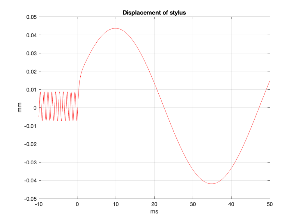
This gives us a good idea of the actual shape of the left wall of the groove in the vinyl for that particular signal.
So, as you can see there, if the connection between the cantilever and the pickup doesn’t have a high enough compliance, it’s no wonder that the needle gets thrown out of the record groove. That’s a heck of a bump to deal with! To be honest, it’s also a little amazing to me that the needle that’s behaving (like the one that produced the output shown in Figure 7) can actually put up with that kind of abuse.
(Special thanks to Jakob Dyreby for helping me to wrap my head around the simulation part of this posting. I did the math, but only after he pointed me in the right direction.)
Post script
Every once in a while, someone will send me a link to a YouTube page that shows an electron microscope “video” of a needle tracking a groove in a vinyl record. If you listen to the explanation of that video, he explains that it’s not really a video. It’s a series of photographs that he took, one by one, and then assembled into a video.
This means that, in that video, the needle isn’t really behaving like it does in real life when the vinyl is moving underneath it.
Imagine setting up a video camera on the side of the road, next to a small speed bump, and making a video of a car driving over it. You’d see that, as the car drives by, the wheels move up into the wheel wells and the car doesn’t get pushed upwards as much, since some of the vertical movement caused by the speed bump is “taken up” by the car’s springs and shock absorbers.
If, instead, you set up a camera, and got the car to move forwards 5 cm and stop – and you take a photo, then the car moves forwards another 5 cm and stops – and you take another photo, and the you repeat this until the car is out of the frame – and then you assemble all of those photos into a video, it would look very different. The car would not remain horizontal when the wheels are on the speed bump because the springs and shock absorbers wouldn’t be compressed at all.
That video is like the second “video” of the car. Of course, it’s still interesting, and it’s well-explained, so no one is playing any tricks on you. But it’s not a video of what actually happens…