This will be another short one.
Part 14 showed the power responses of a theoretical loudspeaker made with two point-sources using a linear-phase crossover using the method that I explained in Part 7.
In Part 11, I showed the power responses when the loudspeaker is made with real drivers in a real enclosure.
This posting shows the same as Part 11, except that I’ve implemented the crossover (at 1 kHz) using linear phase filters (again, with a really long window to avoid any discussion) instead of minimum phase filters.
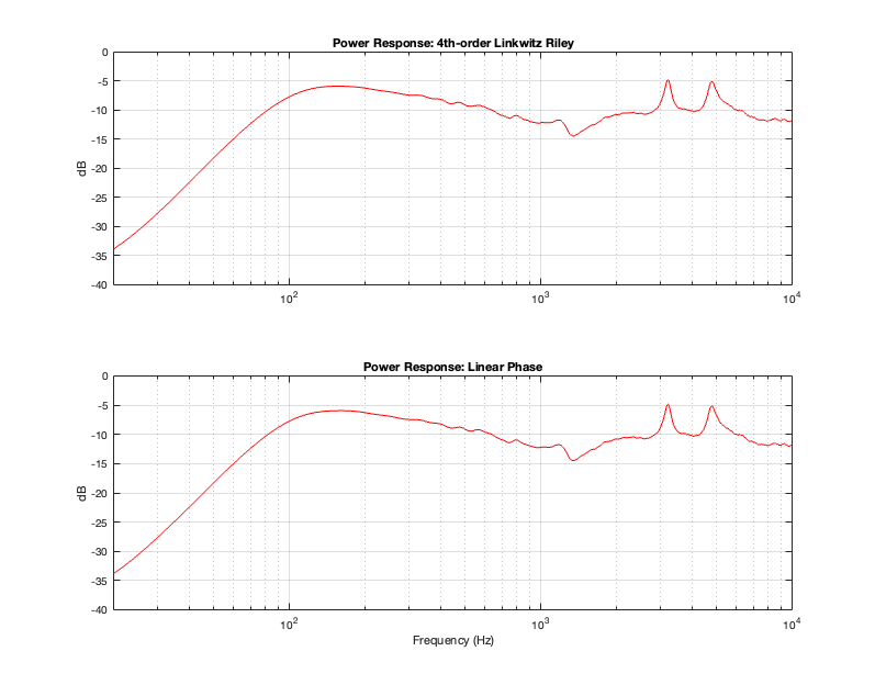
Figure 15.1 shows the real-world power responses of an actual two-way loudspeaker using two crossover strategies. (The top plot was already shown in Part 11.)
Based on the conclusions from Part 14, it should not come as a surprise that a linear phase crossover will result in the same power response as a 4th-order Linkwitz Riley crossover. The only reason I’m showing this here is to prove that the earlier conclusion based on a theoretical simulation holds true in real life.
One important conclusion to make at this point is to realise that a loudspeaker that is implemented with a 4th-order Linkwitz Riley crossover and the same loudspeaker implemented with a linear phase crossover will have identical magnitude responses (in any direction – not just on-axis) and identical power responses. However, they will have different phase responses (in any chosen direction) and different temporal responses (aka impulse responses).