Back to Part 7
As was discussed in Part 3, when a record master is cut on a lathe, the cutter head follows a straight-line path as it moves from the outer rim to the inside of the disk. This means that it is always modulating in a direction that is perpendicular to the groove’s relative direction of travel, regardless of its distance from the centre.
A turntable should be designed to ensure that the stylus tracks the groove made by the cutter head in all aspects. This means that this perpendicular angle should be maintained across the entire surface of the disk. However, in the case of a tonearm that pivots, this is not possible, since the stylus follows a circular path, resulting in an angular tracking error.
The location of the pivot point, the tonearm’s shape, and the mounting of the cartridge can all contribute to reducing this error. Typically, tonearms are designed so that the cartridge is angled to not be in-line with the pivot point. This is done to ensure that there can be two locations on the record’s surface where the stylus is angled correctly relative to the groove.
However, the only real solution is to move the tonearm in a straight line across the disc, maintaining a position that is tangential to the groove, and therefore keeping the stylus located so that its movement is perpendicular to the groove’s relative direction of travel, just as it was with the cutter head on the lathe.
In a perfect system, the movement of the tonearm would be completely synchronous with the sideways “movement” of the groove underneath it, however, this is almost impossible to achieve. In the Beogram 4000c, a detection system is built into the tonearm that responds to the angular deviation from the resting position. The result is that the tonearm “wiggles” across the disk: the groove pulls the stylus towards the centre of the disk for a small distance before the detector reacts and moves the back of the tonearm to correct the angle.
Typically, the distance moved by the stylus before the detector engages the tracking motor is approximately 0.1 mm, which corresponds to a tracking error of approximately 0.044º.
One of the primary artefacts caused by an angular tracking error is distortion of the audio signal: mainly second-order harmonic distortion of sinusoidal tones, and intermodulation distortion on more complex signals. (see “Have Tone Arm Designers Forgotten Their High-School Geometry?” in The Audio Critic, 1:31, Jan./Feb., 1977.) It can be intuitively understood that the distortion is caused by the fact that the stylus is being moved at a different angle than that for which it was designed.
It is possible to calculate an approximate value for this distortion level using the following equation:
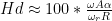
Where 


This equation can be re-written, separating the audio signal from the tonearm behaviour, as shown below.
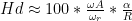
which shows that, for a given audio frequency and disk rotation speed, the audio signal distortion is proportional to the horizontal tracking error over the distance of the stylus to the centre of the disk. (This is the reason one philosophy in the alignment of a pivoting tonearm is to ensure that the tracking error is reduced when approaching the centre of the disk, since the smaller the radius, the greater the distortion.)
It may be confusing as to why the position of the groove on the disk (the radius) has an influence on this value. The reason is that the distortion is dependent on the wavelength of the signal encoded in the groove. The longer the wavelength, the lower the distortion. As was shown in Figure 1 in Part 6 of this series, the wavelength of a constant frequency is longer on the outer groove of the disk than on the inner groove.
Using the Beogram 4000c as an example at its worst-case tracking error of 0.044º: if we have a 1 kHz sine wave with a modulation velocity of 34.1 mm/sec on a 33 1/3 RPM LP on the inner-most groove then the resulting 2nd-harmonic distortion will be 0.7% or about -43 dB relative to the signal. At the outer-most groove (assuming all other variables remain constant), the value will be roughly half of that, at 0.3% or -50 dB.