Fourth-order Linkwitz-Riley
A fourth-order Linkwitz-Riley crossover is made using the same filters in the 2nd-order Butterworth crossover described in the previous posting. The difference in implementation is that you use two second-order filters in series. Again, all filters have the same cutoff frequency and, if you’re implementing them with biquads, the Q of all of them is 1/sqrt(2).
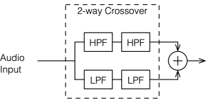
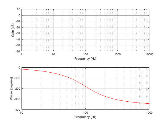
Since we have two high pass filters in series, then the total result is -6 dB at the cutoff frequency (since each of the two filters attenuates by 3 dB) and the slope of the filter is 24 dB per octave. This results in the magnitude and phase responses shown below in Figure 3.2.
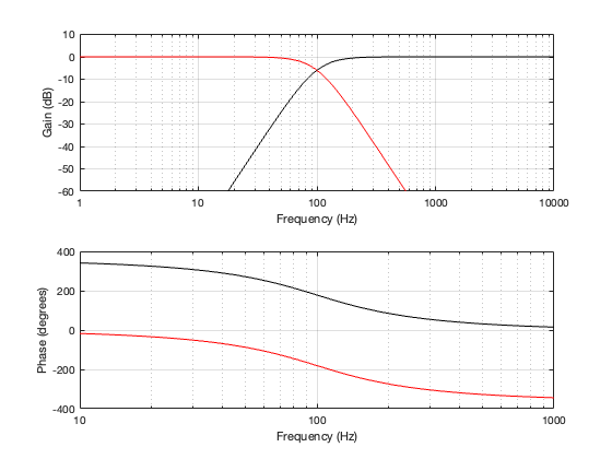
One important thing to notice now is that the phase responses of the two filters are 360º apart at all frequencies. This is different from the second-order Butterworth crossover, in which the two outputs are 180º apart. So we won’t need to flip the polarity of anything to compensate for the phase difference.
As in the previous posting, Let’s look at the signals that get through the crossover, and the total summed output for three input frequencies. This is shown in Figure 3.3, 3.4, and 3.5.
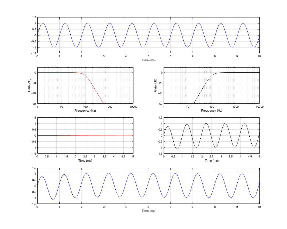
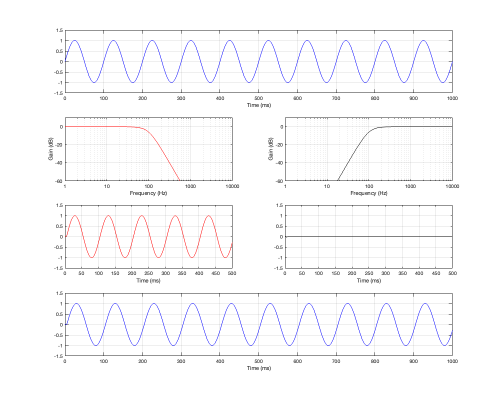
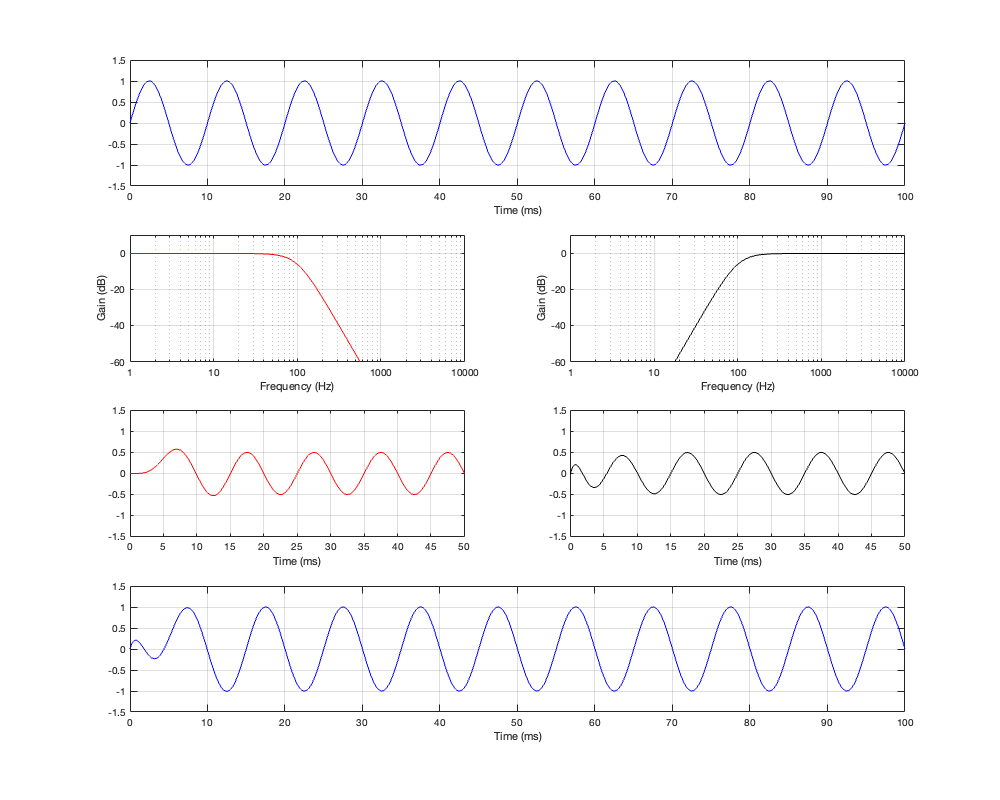
If you take a look at Figures 3.3 and 3.4 it appears that the total summed output of the crossover is in phase with the input at very low and very high frequencies. However, this is actually misleading. Take a look at Figure 3.5 and you’ll see that, when the input signal is the same frequency as the crossover frequency, the summed output is shifted by 180º relative to the input signal.
If we compare the summed output to the input, they are in-phase at very low frequencies. As the frequency increases, the phase of the summed output of the crossover gets later and later, passing 180º at the crossover frequency and approaching a shift of 360º in the high frequencies.
In other words, a 4th-order Linkwitz-Riley crossover by itself, when you sum the outputs of the filters as shown in Figure 3.1, has the same response as a 4th-order minimum phase allpass filter.
One extra thing to notice is that, since the high-pass and low-pass paths are 360º apart, and (partly) since they’re -6 dB at the crossover frequency, the magnitude response of the summed total is flat.