#9 in a series of articles about the technology behind Bang & Olufsen loudspeakers
Recipe for
`Befuddled Speaker Enthusiast´
Makes: One individual with reduced faith in loudspeaker reviews
Total time: approximately 2 hours
Directions
- Take a woofer and put it in a cabinet
- Connect an amplifier to it
- Put it in a sauna
- Set the room temperature to 20° C and wait until everything in the room is the same temperature
- Measure the woofer’s on-axis response with a microphone
- Look at the pretty plot of its magnitude response
- Turn up the thermostat to 100° C and wait until the woofer warms up
- Measure the response again
- Look at the new pretty plot of its magnitude response
- Scratch your head while you ask yourself why the two measurements look so different.
The setup
When you read a magazine review of a loudspeaker, it will include a measurement of its “frequency response” (more accurately called its “magnitude response”) which shows (ignoring a bunch of things) how loud different frequencies are when they come out of the loudspeaker assuming that they all came in at the same level.
However, as we saw in a previous article, for a Bang & Olufsen loudspeaker, this magnitude response is dependent not only on the loudspeaker, but how loudly you’re playing the signal.
Unfortunately, it gets much worse than this… For example, if we take a woofer (say, the one from the recipe above, for example) we can explain its electromechanical characteristics by breaking it down into different components (both actual and analogical). For example, the suspension (which is comprised of the surround and the spider) can be thought of as a spring. The electrical analogy for this is a capacitor. If you take all of the moving parts in the loudspeaker driver, they all add up to a mass that has to be moved – the electrical analogy for that mass is an inductor (since an inductor has some electrical “inertia” just like the mass of a bunch of loudspeaker bits). Some of the components are not an electrical analogy – they are real electrical components. For example, the voice coil, since it’s a coil, acts as an inductor. And, since it is a thin bit of wire, it also has some resistance to the flow of electrical current through it, so it’s also a resistor.
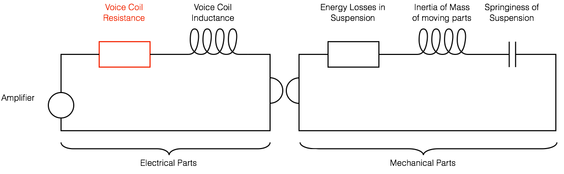
If you look at the diagram above, you’ll see a very simplified “circuit” that shows the components of a moving coil dynamic loudspeaker. If these components don’t look familiar to you, don’t worry, it’s not important. Some components in the circuit are actual electrical things (like the resistance of the voice coil, shown in red) and others are analogies – electrical representations for a mechanical component in the system (such as a capacitor representing the “spring” of the surround and the spider).
If you know how each of these components behaves, and you know the correct values to put in for a given loudspeaker, and you know how to do the right math, then you can come pretty close to getting a decent prediction of the response of the loudspeaker that you’re modelling with the circuit. However, if you just put in one value for each component, then you’re assuming that they never change – in other words that you’re dealing with a “linear” system.
The problem is that this assumption is incorrect. For example, the Voice Coil Resistance – the amount that the wire in the voice coil resists the flow of current through it when the loudspeaker driver is not moving – changes with temperature. The hotter the wire gets, the higher the resistance goes. (This is a normal behaviour for most resistors.) If the voice coil resistance changes, then the whole system behaves differently, since it isn’t the only component in the circuit. So, as we change the temperature of the voice coil, the total response of the loudspeaker changes.
Sadly, the temperature of the voice coil isn’t only dependent on the room temperature as it seemed to be in our recipe for a Befuddled Speaker Enthusiast. As soon as you start playing sound with a loudspeaker, it starts heating up. The louder the signal (either because you turned up the volume or because your Metallica album just came on) the hotter it gets. So as you play music, it heats and cools. The speed with which it heats up and cools down is dependent on its “thermal time constant” – a big woofer with a giant magnet will take longer to heat up and cool down (and therefore have a longer thermal time constant) than a little tiny tweeter.
So, now you should have at least three questions that deserve answers:
- How much does the temperature vary when I play music?
- How does the response of the loudspeaker change with temperature?
- How much does the response of the loudspeaker change with temperature?
- What are you going to do about it?
1. Voice coil temperature
As I’ve talked about in a previous article, a loudspeaker driver is, give or take, about 1% efficient. That means that 99% of the power that you push into it (from the amplifier) is not converted into sound. Unfortunately, all of that power is lost as heat – almost all of it at the voice coil of the loudspeaker. So, the louder your music, the hotter your voice coil gets. Of course, if you have a way of cooling it (by using other parts of the loudspeaker as a radiator to your listening room) then it won’t get as hot, and it will cool down faster.
Let’s take a BeoLab 5 as an example (since that’s where we’re headed anyway…). Let’s take some relatively new-ish pop music (which has been mastered to be fairly loud due to a war that has been going on for years) and play it on a B&O player through Power Link (B&O’s version of a line level signal) at maximum volume on a BeoLab 5 whilst monitoring the temperature of the voice coils. What you’ll see if you do this is something like the plot below.
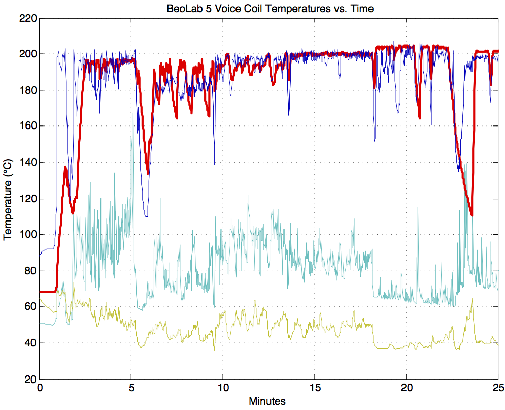
As you can see in the screenshot in Figure 2, the lower woofer (a 15″ driver connected to a 1000 W Ice Power amplifier) varied with a maximum of about 205° C. While it was playing this music at this level, it rarely dropped below 120°C.
This means that the difference in temperature of the woofer was 185°C at a maximum (205°C – 20°C) and rarely below 100°C.
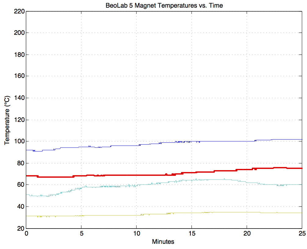
In case you are wondering, this temperature cannot be measured directly, since it would destroy the voice coil if we tried to do so. Instead, what we do is to measure the temperature of the loudspeaker driver magnets, and use that real-time data input in addition to the signal that we’re sending to the drivers to calculate the temperatures of the voice coils based on thermal models of each of them. As you can see in Figure 3, below, the magnet temperatures are very different, and react much more slowly. These measurements were taken at exactly the same time as the ones shown in Figure 2. (Note that, although the mid woofer and woofer voice coils are roughly the same temperature, the mid woofer magnet is hotter than the woofer magnet by about 20°C or so. This just proves that their thermal models are different.)
2 & 3. Loudspeaker response changes
So, now the question is “what does this change in temperature do to the response of the driver?” We’ll only deal with one driver – the woofer.
As I mentioned above, the thing that changes most in the model shown in Figure 1 is the loudspeaker driver’s voice coil resistance. For those of you with a background in reading electrical circuits, you may notice that the one shown in Figure 1 has some reactive components in it which will result in a resonance at some frequency. For those of you without a background in reading electrical circuits, what this means is that a loudspeaker driver (like a woofer) has some frequency that it “wants” to ring at – if you thump it with your thumb, that’s the frequency that you will hear ringing – a bit like a bell with a low pitch.
As the voice coil resistance goes up, its resistance increases, and we generally lose sensitivity (i.e. level or loudness) from the woofer. In other words, the hotter it gets, the quieter it gets. However, this only happens at the frequencies where the resistor is not “overridden” by another component – say the mechanical resonance of the woofer or the inductance of the voice coil.
The total result is shown for various temperature differences in Figure 4. Notice that these plots show the change in magnitude response of the driver with CHANGES in temperature. So, the blue curve at the top is the change in magnitude response (which is 0 dB at all frequencies – in other words no change) when the loudspeaker is playing at the same temperature it was measured at (let’s say, 20°C or room temperature). As the temperature of the voice coil increases above that temperature, you can see that you lose output in two frequency bands on either side of a “bump” in the response – this is at the resonant frequency of the loudspeaker driver.
So, the louder you play, the more low end you lose, apart from a peak in the response (which also rings in time) at the resonant frequency of the driver.
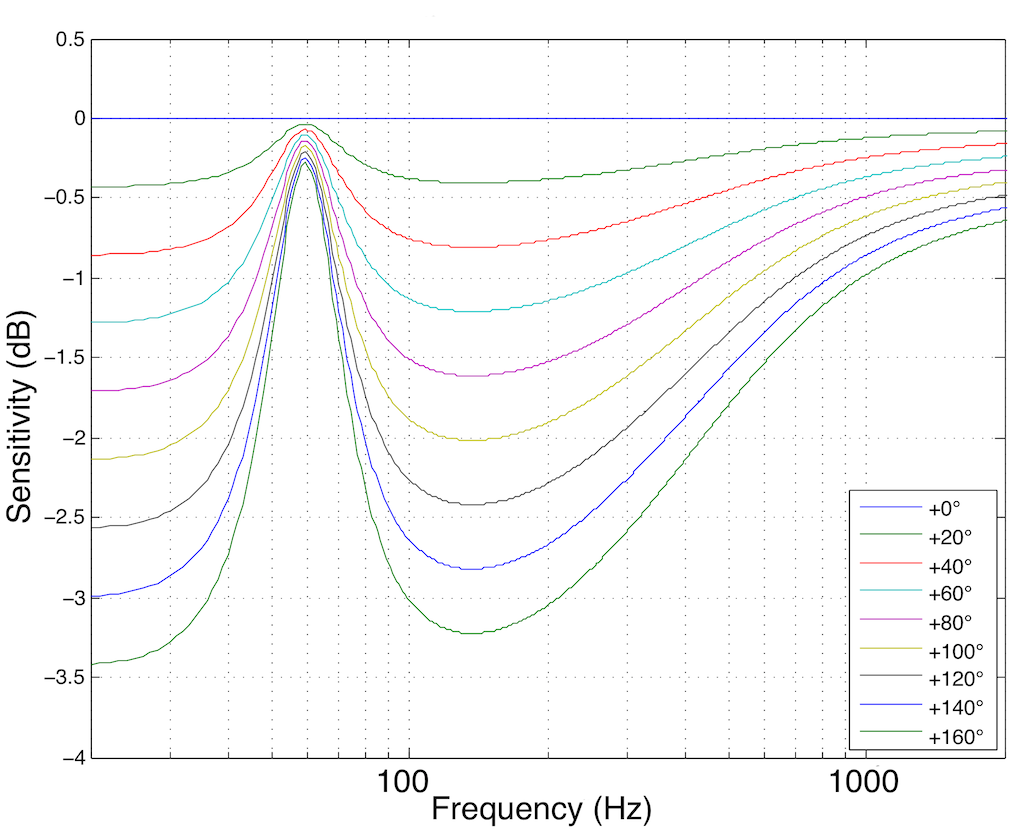
In case you’re wondering, the plot shown in Figure 4 is pretty close to the actual response of the 15″ woofer in the BeoLab 5 at different temperatures above room temperature.
The solution
Interestingly, all of the stuff I said above is true for every loudspeaker. So, if you’re the kind of person who believes that the only proper loudspeaker is one where you have nothing but a loudspeaker driver (in a cabinet of any kind, or not) and an amplifier – and no weird filtering or mucking-about going on, then you’ll have to live with the kind of unpredictable behaviour that you see above. This happens all the time to every dynamic loudspeaker. Since, in a passive loudspeaker, there’s nothing you can do about this (except for trying to keep the drivers cool somehow) you don’t often hear passive loudspeaker manufacturers talking about this little skeleton in their closet…
However, since a BeoLab 5 “knows” the temperature of the voice coil of the woofer, and since it has been programmed with the curves shown above in Figure 4, we can do something about it.
In essence all we need to do is to take Figure 4, flip it upside down and make a filter that “undoes” the effect of temperature on the loudspeaker’s response. In other words, if (because the woofer gets 160°C above “normal”) it drops 3 dB at 20 Hz, the BeoLab 5 knows this and adds 3 dB at 20 Hz. So, built into the BeoLab 5 is a set of filters that are used, depending on the temperature of the woofer’s voice coil. These filters are shown in Figure 5.

It’s important to note three things here.
- This can be done because we know the behaviour of the woofer at different temperatures (this was measured as part of the development process)
- This can be done because the loudspeaker “brain” (the DSP) knows the temperature of the voice coil in real time as you’re playing music
- This filter should only be applied to the woofer. The mid woofer and the other drivers have different behaviours and should not be affected by this correction curve. Therefore, this filtering can only be done because the BeoLab 5 is an active loudspeaker with independent filtering for each loudspeaker driver.
Some extra information
You should be left with at least one question. I said above that, as the music gets loud, the woofer heats up, so you lose output, so we add a filter that compensates by putting more signal into the driver.
“Waitaminute!” I hear you cry… “The problem is caused by the signal being too loud, so you make it louder!?” Well… yes.
However, there is one more trick up our sleeve. In a previous posting, I mentioned in passing that we also have Thermal Protection in almost all of the loudspeakers in the B&O portfolio. This means that the DSP brain knows the temperature of the drivers and, in a worst-case situation, turns the levels down to protect things from burning up. So, if we go back to the example of a BeoLab 5 playing at full volume, let’s see what’s happening to the signal levels.

These curves in Figure 6 show the gains applied to the four loudspeaker drivers in a BeoLab 5 at the same time as the measurements shown in Figures 2 and 3 were being made. In fact, if you look carefully at Figure 2 around the 23 minute mark, you’ll see that the temperature dropped – which is why the gain in Figure 6 increases (because it can!) in response.
Now, don’t panic. The BeoLab 5 isn’t screwing around with the gains of the drivers all the time. Remember that this test was done at FULL VOLUME – which, for a BeoLAb 5 is VERY LOUD. The gains shown in Figure 6 are a last-ditch effort of the loudspeaker to protect itself from a very mean customer (or the very mean children of a customer who is away for the weekend). This is the equivalent of the airbags deploying in your car. You know that if the airbags are outside the steering wheel (or if the gains in the BeoLab 5 dropped by 15 dB or so) something significant occurred…
Thanks to Gert Munch for his help in cleaning up the mistakes I made in the drafts up to and including the penultimate version of this article.
oluv says:
ok, i think this posting cleared it up for me a little bit, i mean the temperature vs. frequency response measurement idea. but these are extreme values like 200° temperature change. But also 20 or 30°C change should affect the response considerably according to your graphs. do you hear this change in sound?
geoff says:
Hi,
The temperature in these graphs is the temperature of the voice coil. The temperature you talk about in the comment in the other posting is more related to the effects of cold/warm on the surround and spider. For example, this (the stiffness of the suspension) is an issue with temperature extremes in automotive loudspeakers where ranges of -30 deg C to +140 deg C are “normal”.
Also remember that the graphs shown here are not temperature – they are change in temperature.
Whether or not the change in a driver’s magnitude response for a given change in voice coil temperature is audible is dependent on many things like (but not exclusive to):
– where you’ve changed from (for example, a delta of 0 to 10 is not the same as 100 to 110)
– what the particular characteristics of the driver in question are (different drivers have different changes in magnitude response with temperature)
– the thermal constant of the driver (how quickly it heats up and cools down)
– the spectral content of the signal to which you’re listening
– the dynamic profile (or envelope) of the signal to which you’re listening (which will also have an effect on the temperature changes in time of the driver)
The important thing to remember here is that the entire system is changing all the time – at least if we only restrict ourselves to talking about the magnitude response changes as a result of voice coil temperature changes. Other things are also happening – this is just one dimension of a multi-dimensional problem.
As Josh Reiss once said (albeit somewhat facetiously) at an AES convention, there’s no point in measuring a loudspeaker, because as soon as you finish measuring it, it’s a different loudspeaker… Wolfgang Klippel might disagree… :-)
Cheers
-geoff
oluv says:
a technically profound and detailed response by a real “tonmeister”.
thanks for clarification!
Erin says:
Really nice article here. Is it reasonable to assume the temperature effects are minimized on the tweeter and the midrange because there’s a high-pass filter being used, keeping the driver’s passband out of Fs territory?
geoff says:
Hi,
The temperature effects are different – but they’re not necessarily minimised.
The graphs I show here are for a woofer in free air – so the resonant frequency is the Fs of the driver itself. However, that would move if the driver were in a cabinet. You’d also see at least one other resonance if the driver were in a ported cabinet.
However, notice that the sensitivity effects are actually the smallest at Fs – because the driver is most efficient at that frequency. The problem occurs at frequencies where the driver efficiency is lower – away from Fs.
Hope this helps.
Cheers
-geoff
Erin says:
Thanks for the reply.
Nice site here, by the way. I am gonna have to do some more reading when I get free time… whenever that happens. ;)