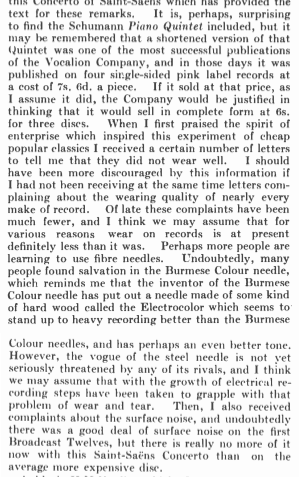
What caught my eye was the discussion of gramophone needles made of “hard wood”, and also the prediction that “the growth of electrical recording steps … to grapple with that problem of wear and tear.”
The fact that electrical (instead of mechanical) recording and playback was seen as a solution to “wear and tear” reminded me of my first textbook in Sound Recording where “Digital Audio” was introduced only within the chapter on Noise Reduction.
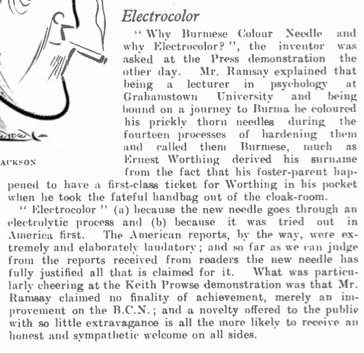
Later in that same issue, there is a little explanation of the “Electrocolor” and “Burmese” needles.
The March 1935 issue raises the point of wear vs. fidelity in the Editorial (which starts by comparing players with over-sized horns).
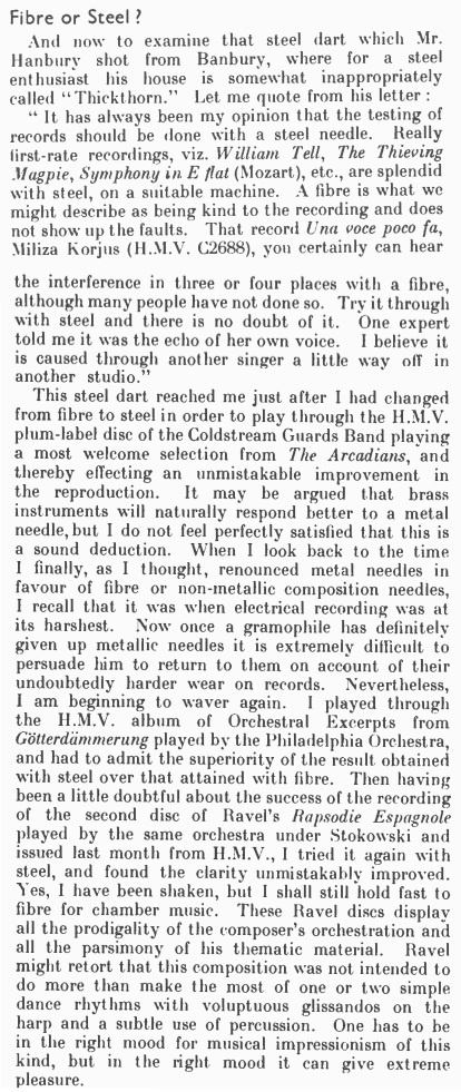
I like the comment about having to be in the “right mood” for Ravel. Some things never change.
What’s funny is that, now that I’ve seen this, I can’t NOT see it. There are advertisements for fibre, thorn, and wood needles all over the place in 1930s audio magazines.
Late-night free-floating anxiety is not a modern phenomenon. One of my favourite descriptions of it is Dorothy Parker’s 1933 short story called “The Little Hours”, published in The New Yorker.
However, more than 30 years before this, The Phono Gram magazine published the following, which a Dr. J. Leonard Corning proposed to cure the problem of late-night melancholy with what we would, today, called a “pair of headphones” (although the design that he describes probably wouldn’t sell well to anyone who is not interested in S&M…) playing Wagnerian arpeggios and minor chords. (Personally, I just put the timer on my iPhone to turn off after 30 minutes, and turn on an old episode of “QI” or “8 Out of 10 Cats Does Countdown” – Sean Lock’s voice drowns out my own internal ones.)
I live in Denmark where people speak Danish. One interesting word that I use every day is “højtaler” which is the Danish word for “loudspeaker”. I say that this word is “interesting” because, just like “loudspeaker” it is actually two words glued together. “Høj” means “high” or “loud” and “taler” means “talker” or “speaker” (as in “the person who is doing the talking”).
Sometimes, when I have a couple of minutes to spare, instead of looking at cat videos on YouTube, I sift through old audio and electronics magazines for fun. One really good source for these is the collection at worldradiohistory.com. (archive.org is also good!). Today I stumbled across the December, 1921 edition of Practical Electrics Magazine (which changed its name to The Experimenter in November of 1924 and then to Amazing Stories in April 1926*) It had a short description of a stage trick called the “Haunted Violin”, an excerpt from which is shown below.
The trick was that a violin, held by a woman walking around the aisle of the theatre would appear to play itself. In fact, as you can see above, there was an incognito violinist with a “detectophone” that was transmitting through wires connected to metal plates under the carpet in the theatre. The woman was wearing shoes with heels pointy enough to pierce the carpet and make contact with the plates. The heels were then connected with wires running through her dress to a “loud talker” hidden inside the violin.
Seems that, in 1921, it would have been easier to learn at least one word in Danish…
Side note: This is why, when I’m writing about audio systems I try as hard as possible to always use the word “loudspeaker” instead of “speaker”. To me, a “speaker” is a person giving a speech. A “loudspeaker” is a thing I complain about every day at work.
* That April 1926 edition of Amazing Stories had short stories by Jules Verne, H.G. Wells, and Edgar Allan Poe!
Post Script: My wife reminded me that it’s the same in French: “haut-parleur”. It’s a reminder that the original loudspeakers were never intended for music, I suppose…
I know that language evolves. I know that a dictionary is a record of how we use words; not an arbiter of how words should be used. However, I also believe very firmly that if you don’t use words correctly, then you won’t be saying what you mean, and therefore you can be misconstrued.
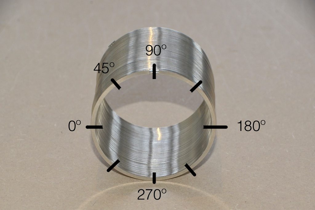
One of the more common phrases that you’ll hear audio people use is “out of phase” when they mean “180º out of phase” or possibly even “opposite polarity”. I recently heard someone I work with say “out of phase” and I corrected them and said “you mean ‘opposite polarity'” and so a discussion began around the question of whether “180º out of phase” and “opposite polarity” can possibly result in two different things, or whether they’re interchangeable.
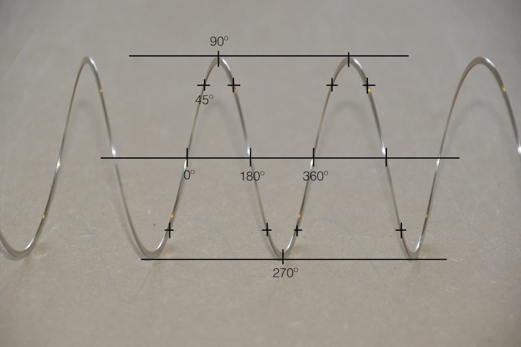
Let’s start by talking about what “phase” is. When you look at a sine wave, you’re essentially looking at a two-dimensional view of a three-dimensional shape. I’ve talked about this a lot in two other postings: this one and this one. However, the short form goes something like “Look at a coil spring from the side and it will look like a sine wave.” A coil is a two-dimensional circle that has been stretched in the third dimension so that when you rotate 360º, you wind up back where you started in the first two dimensions, but not the third. When you look at that coil from the side, the circular rotation (say, in degrees) looks like a change in height.
Figure 1Figure 2
Notice in the two photos above how the rotation of the circle, when viewed from the side, looks only like a change in height related to the rotation in degrees.
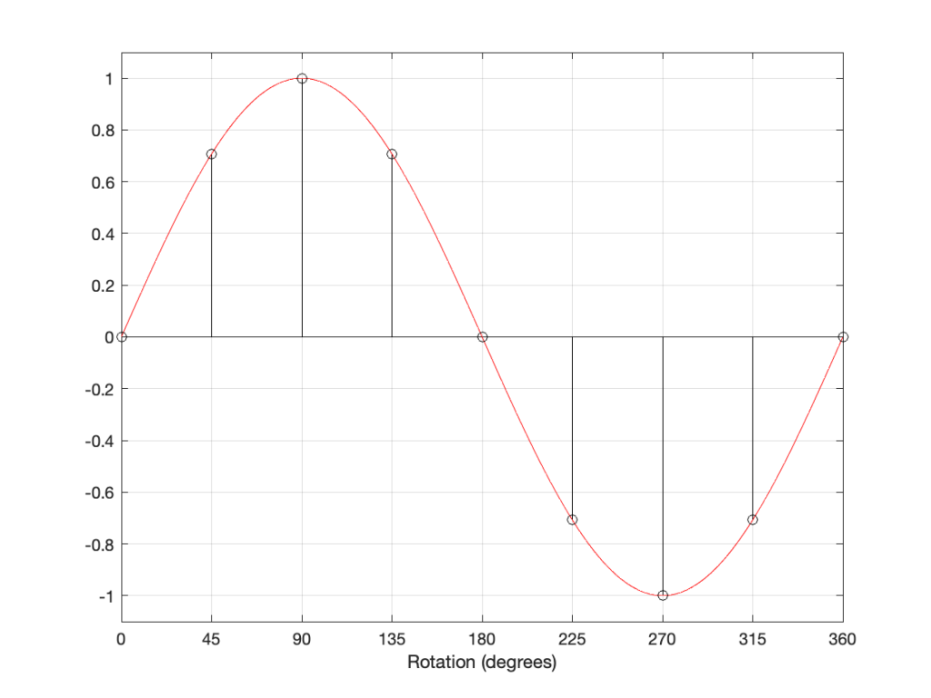
Figure 3
The figure above is a classic representation of a sine wave with a peak amplitude of 1, and as you can see there, it’s essentially the same as the photo of the Slinky. In fact, you get used to seeing sine waves as springs-viewed-from-the-side if you force yourself to think of it that way.
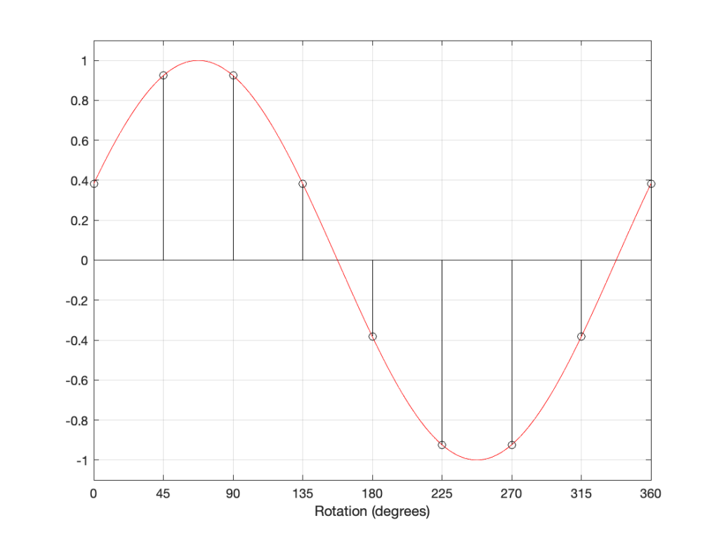
Now let’s look at the same sine wave, but we’ll start at a different place in the rotation.
Figure 4
The figure above shows a sine wave whose rotation has been delayed by some number of degrees (22.5º, to be precisely accurate).
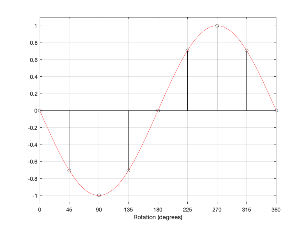
If I delay the start of the sine wave by 180 degrees instead, it looks like Figure 5..
Figure 5
However, if I take the sine wave and multiply each value by -1 (inverting the polarity) then it looks like this:
Figure 6
As you can probably see, the plots in Figure 5 and 6 are identical. Therefore, in the case of a sine wave, shifting the phase of the signal by 180 degrees has the same result at inverting the polarity.
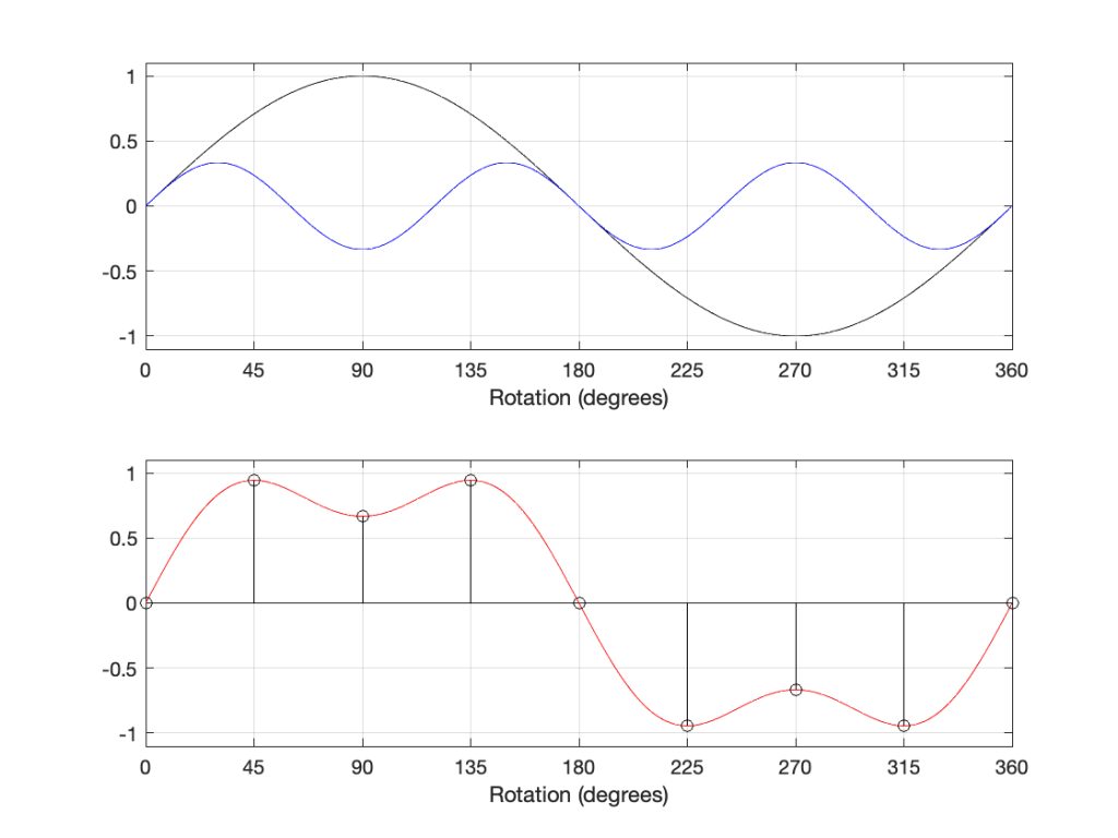
What happens when you have a signal that is the sum of multiple sine waves? Let’s look at a simple example below.
Figure 7
The top plot above shows two sine waves, one with a frequency of three times the other, and with 1/3 the amplitude. If I add these two together, the result is the red curve in the lower plot. There are two ways to think of this addition: You can add each amplitude, degree by degree to get the red curve. You can also think of the slopes adding. At the 180º mark, the two downward-going slopes of the two sine waves cause the steeper slope in the red curve.
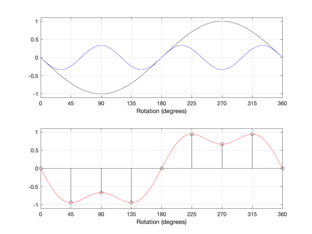
If we shift the phase of each of the two sine wave components, then the result looks like the plots below.
Figure 8
As you can see in the plots above, shifting the phases of the sine waves is the same as inverting their polarities, and so the resulting total sum (the red curve) is the same as if we had inverted the polarity of the previous total sum.
So, so far, we can conclude that shifting the phase by 180º gives the same result as inverting the polarity.
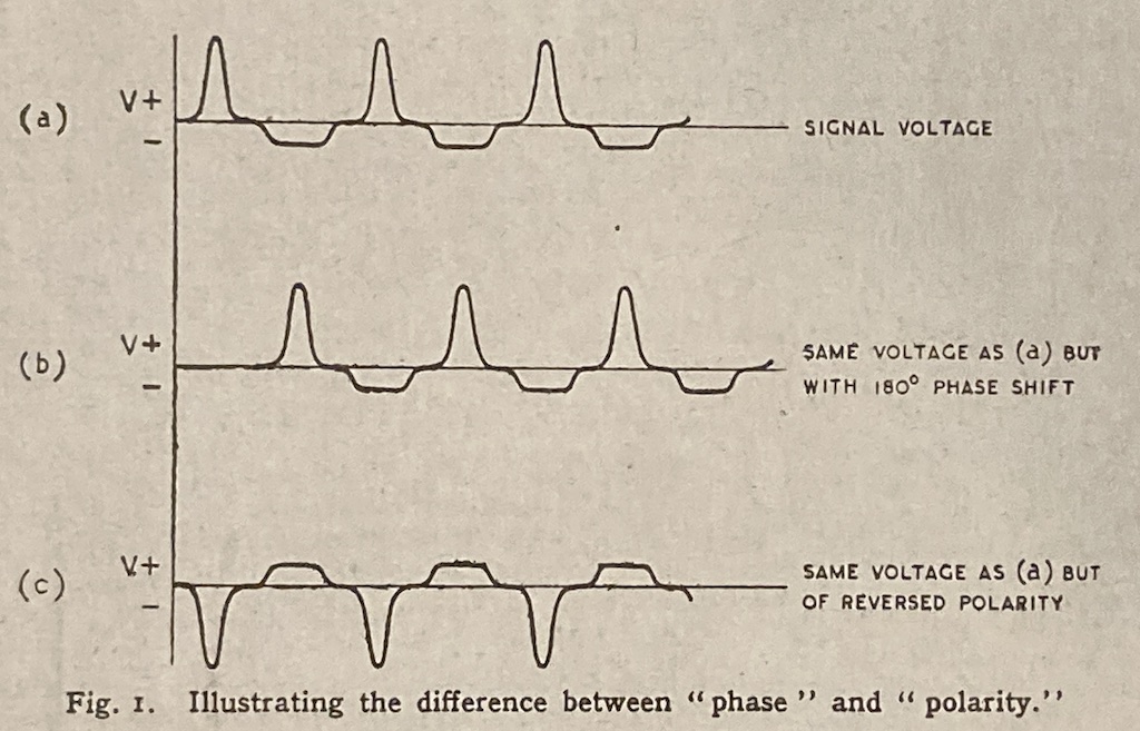
In the April, 1946 edition of Wireless World magazine, C.E. Cooper wrote an article called “Phase Relationships: ‘180 Degrees Out of Phase’ or ‘Reversed Polarity’?” (I’m not the first one to have this debate…) In this article, it’s states that there is a difference between “phase” and “polarity” with the example shown below.
Figure 9
There is a problem with the illustration in Figure 9, which is the fact that you cannot say that the middle plot has been shifted in phase by 180 degrees because that waveform doesn’t have a “phase”. If you decomposed it to its constituent sines/cosines and shifted each of those by 180º, then the result would look like (c) instead of (b). Instead, this signal has had a delay of 1/2 of a period applied to it – which is a different thing, since it’s delaying in time instead of shifting in phase.
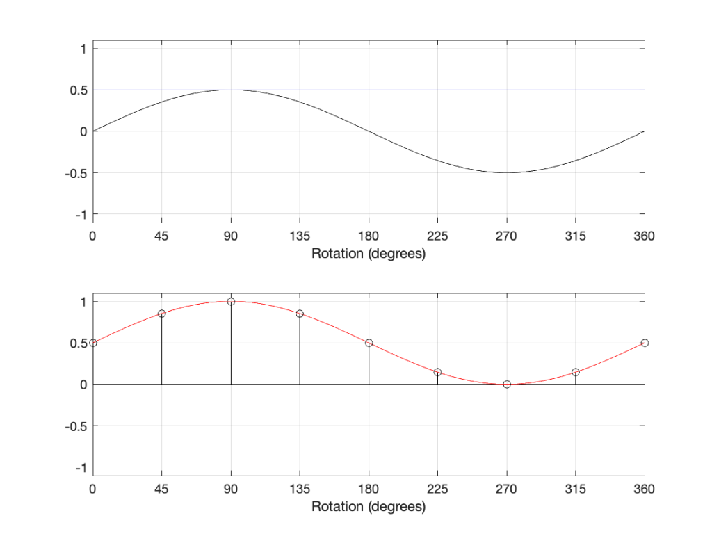
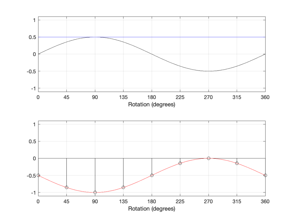
However, there is a hint here of a correct answer… If we think of the black and blue sine waves in the 2-part plots above as sine waves with frequencies 1 Hz and 3 Hz, we can add another “sine wave” with a frequency of 0 Hz, or DC, as shown in Figure 10, below.
Figure 10
In the plot above, the top plot has a DC component (the blue line) that is added to the sine component (the black curve) resulting in a sine wave with a DC offset (the red curve).
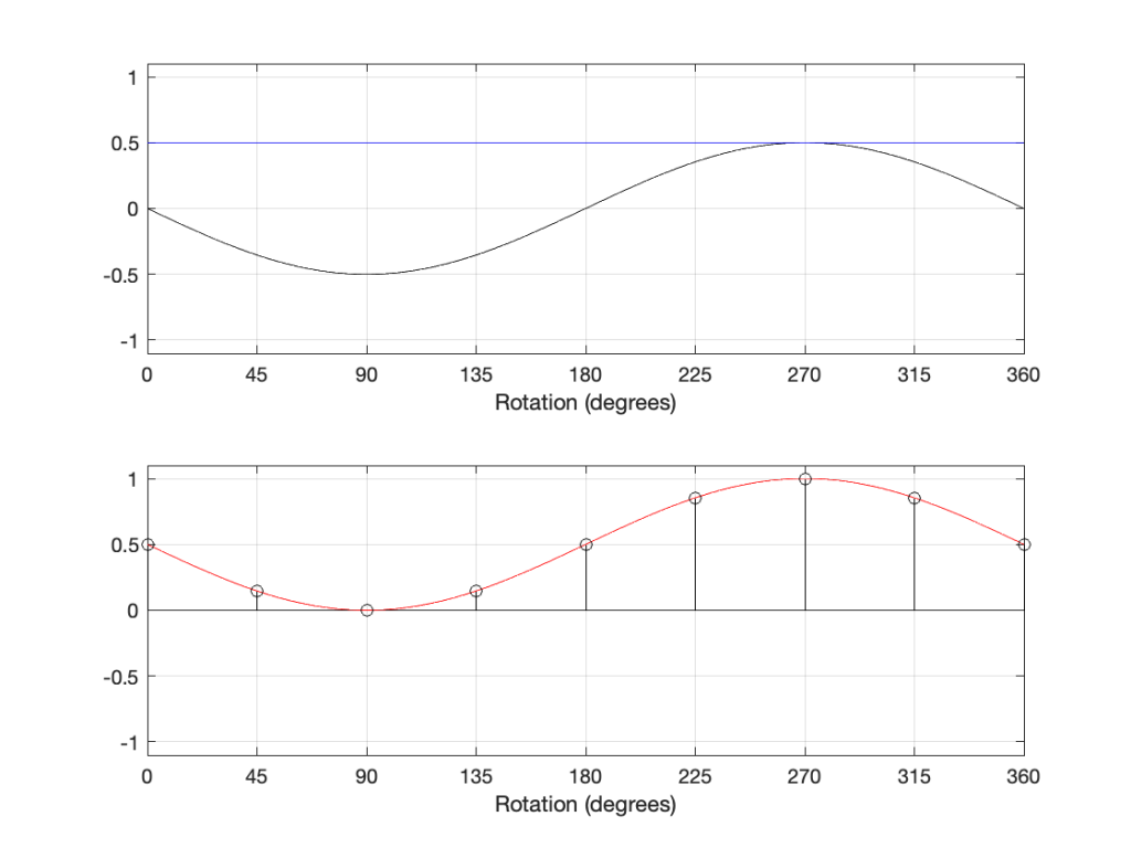
If we invert the polarity of this signal, then the result is as shown in Figure 11.
Figure 11
However, if we delay the components by 180º, the result is different, as shown in Figure 12:
Figure 12
The hint from the 1946 article was the addition of a DC offset to the signal. If we think of that as a sine wave with a frequency of 0 Hz, then it can be “phase-shifted” by 180º which results in the same value instead of inverting polarity.
However, to be fair, most of the time, shifting the phase by 180º gives the same result as inverting the polarity. However, I still don’t like it when people say “flip the phase”…
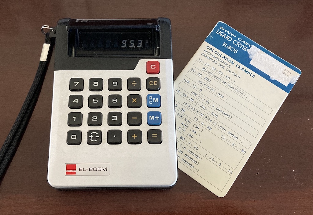
I found this at a flea market yesterday and I couldn’t resist buying it. It’s a Sharp EL-805M “pocket” calculator that was released for sale in 1973 and discontinued in 1974.
This would have been a time when a Liquid Crystal display was a feature worth advertising on the front panel of the calculator (since this was the first calculator with an LCD).
Sharp was one of the pioneers of calculators using the DSM (Dynamic Scattering Mode) LCD (Liquid Crystal Display). These DSM LCDs have the now unusual feature of silver-like reflective digits on a dark background, rather than the now common black digits on a light background.
It was also from a time when instructions were included on how to use it. Notice the instructions for calculating 25 x 36, for example…
Undoubtably, the best 20 DKK I spent all weekend, given that the original price in 1973 was 110 USD.
For a peek inside, this site has some good shots, but it seems that it proves to be a challenge for automatic translators. There’s also a good history here.
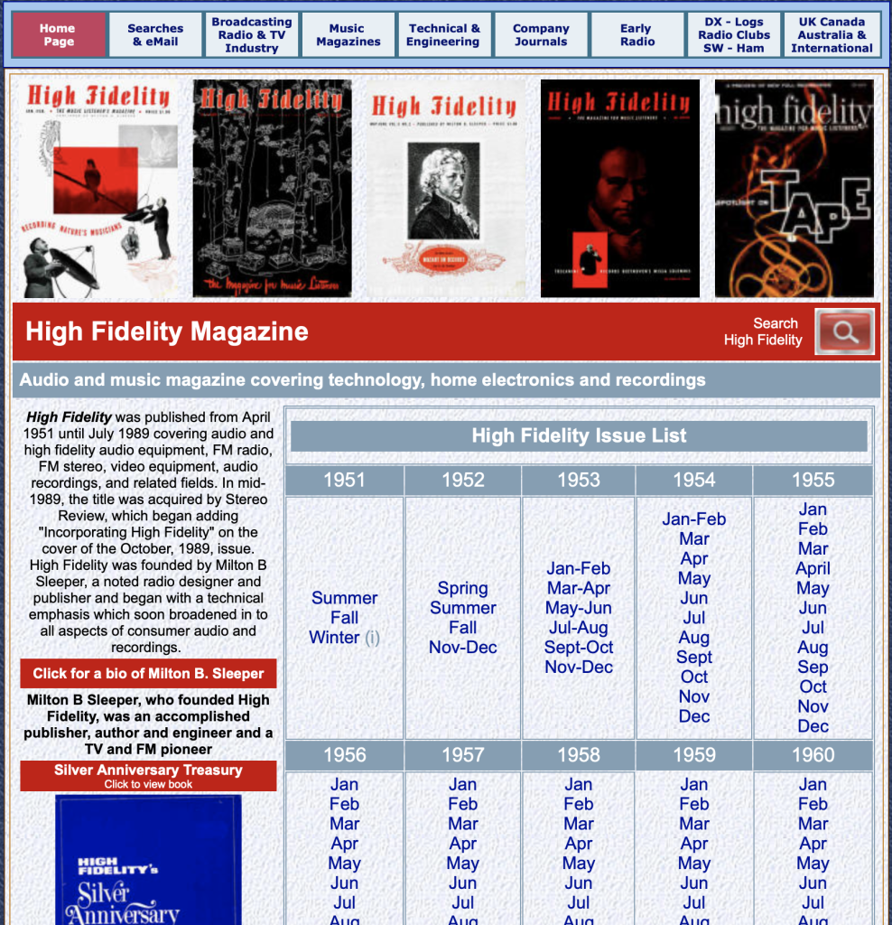
This is a radio show by Glenn Gould from 1965 that is the audio version which was expanded by Gould into an article written for High Fidelity magazine’s 15th anniversary edition (which can be downloaded from this site. The article starts on page 46.)