#13 in a series of articles about the technology behind Bang & Olufsen loudspeakers
The following question recently arrived in my inbox via our customer service department.
“I am an admirer of B&O Hifi products as of over 20 years, but a great mystery for me is how you achieve great sound reproduction in the typically minimalist Scandinavian interior design environmment with polished floors, bare walls and bare glass windows. Effectively such environments are acoustical disasters !?!”
- early reflections
- room modes
- reverberation
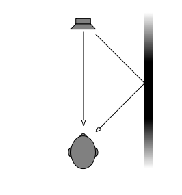
Early Reflections


- move the loudspeaker very close to the wall
- move the loudspeaker farther front the wall
- sit very close to the wall
- sit farther away from the wall
- put absorption on the wall
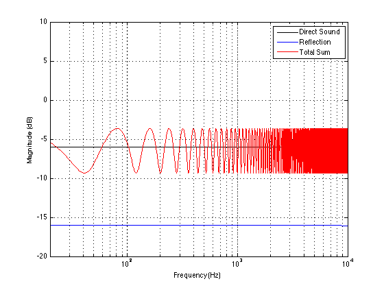
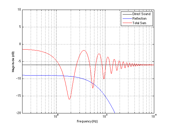
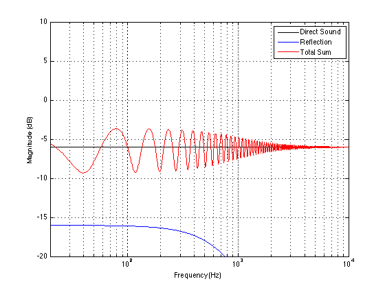
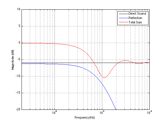
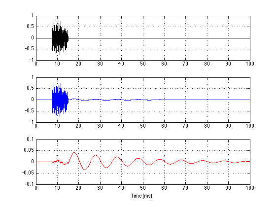
However, there is one interesting effect that sits on top of all of this – that is the fact that what you’ll see in a measurement with a microphone is not necessarily representative of what you’ll hear. This is because a microphone does not have two ears. Also, the direction the reflection comes from will change how you perceive it. A sidewall reflection sounds different from a floor reflection. This is because you have two ears – one on each side of your head. Your brain uses the sidewall reflections (or, more precisely, how they relate to the direct sound) to determine, in part, how far away a sound source is. Also, since, in the case of sidewall reflections, your two ears get two different delay times on the reflection (usually), you get two different comb-filter patterns, where the peaks in one ear can be used to fill in the notches in the other ear and vice versa. When the reflection comes from the floor or ceiling, your two ears get the same artefacts (since your two ears are the same distance to the floor, probably). Consequently, it’s easily noticeable (and it’s been proven using science!) that a floor or ceiling reflection has a bigger timbral effect on a loudspeaker than a lateral (or sideways) reflection.
Room modes
There are two audible effects of this. The first is that, if your music contains the frequency that the room wants to resonate at, then that note will sound louder. When you hear people talk of “uneven bass” or a “one-note-bass” effect, one of the first suspects to blame is a room mode.
The second is that, since the mode is ringing along with the music, the overall effect will be muddiness. This is particularly true when one bass note causes the room mode to start ringing, and it keeps ringing when the next bass note is playing. For example, if your room rings on a C#, and the bass plays a C# followed by a D – then the room will be ringing at C#, conflicting with the D and resulting in mud. This is also true if the kick drum triggers the room mode, so you have a kick drum “plucking” the room ringing on a C# all through the track. If the tune is in the key of F, then this will not be pretty.
If you would like to calculate a prediction of where you’ll have a problem with a room mode, you can just do the following math:
metric version: room mode frequency in Hz = 172 / (room length in metres)
imperial version: room mode frequency in Hz = 558 / (room length in feet)
Your worst modes will be the frequencies calculated using either of the equations above, and multiples of them (i.e. 2 times the result, 3 times the result, and so on).
So, for example, if your room is 5 m wide, your worst-case modes will be at 172 / 5 = 34.4 Hz, as well as 68.8 Hz, 103.2 Hz and so on. Remember that these are just predictions – but they’ll come pretty close. You should also remember that this assumes that you have completely immovable walls and no absorption – if this is not true, then the mode might not be a problem at all. (If you would like to do a more thorough modal analysis of your listening room, check out this page as a good start.)
Sadly, there is not much you can do about room modes. There are ways to manage them, including, but not exclusive to the following strategies:
- make sure that the three dimensions of your listening room are not related to each other with simple ratios
- put up membrane absorbers or slot absorbers that are tuned to the modal frequencies
- place your loudspeaker in a node – a location in a room where it does not couple to a problematic mode (however, note that one mode’s node is another mode’s antinode)
- sit in a node – a location in a room where you do not couple to a problematic mode (see warning above…)
- use room correction DSP software such as ABC in the BeoLab 5
Reverberation
Reverberation is what you hear when you clap your hands in a big cathedral. It’s the collection of a lot of reflections bouncing from everywhere as you go through time. When you first clap your hands, you get a couple of reflections that come in separated enough in time that they get their own label – “early reflections”. After that, there are so many reflections coming from so many directions, and so densely packed together in time, that we can’t separate them, so we just call them “reverberation” or “reverb” (although you’ll often hear people call it “echo” which is the wrong word to use for this.
Reverb is what you get when you have a lot of reflective surfaces in your room – but since it’s so irregular in time and space, it just makes a wash of sound rather than a weird comb-filter effect like we saw with a single reflection. So, although it makes things “cloudy” – it’s more like having a fog on your glasses instead of a scratch. Think of it like the soft focus effect that was applied to all attractive alien women on the original Star Trek – you lose the details, but it’s not necessarily a bad thing.
So what are you gonna do about it?
Fine, this is a short-form version of what a room’s acoustics does to the sound of a loudspeaker, but how do we, as a manufacturer of loudspeakers, ensure that our products can withstand the abuse that your listening room will apply to the sound? Well, there are a number of strategies that we use to do what we can…
1. ABC. The BeoLab 5 has a proprietary system built-in called Adaptive Bass Control or ABC. Pressing a button at the top of the loudspeaker starts a measurement procedure that is performed using a built-in microphone that measures the loudspeaker’s behaviour in two locations. Actually, what it’s doing is looking at the difference in the loudspeaker’s response in those two positions of the microphone to determine the radiation resistance that the loudspeaker “sees” as a result of reflective surfaces in the room. The ABC algorithm then creates a filter that is used to “undo” the effects of some of the low-frequency effects of the room’s acoustics. For example, if the radiation resistance indicates that the loudspeaker is close to a wall (which, as we saw above, will boost the bass) then the filter will reduce the bass symmetrically. That way, the loss in the filter and the gain due to the wall will cancel each other.
2. Position switches. ABC in the BeoLab 5 is a very customised filter that, in part, will adjust the loudspeaker’s response for placement near a wall or in a corner. Almost all of the other BeoLab loudspeakers (and other sound systems such as the BeoPlay A8 and A9, for example), include a manual-adjusted “position switch”. This allows you to use one of three filters that we have customised in the development of the loudspeaker to account for its behaviour according to whether you have placed it away from a reflective surface (“Free”), near one surface (“Wall”) or in a Corner. This is not just a filter that adjusts the bass level. The three filters for “free”, “wall”, and “corner” have been calculated using three dimensional measurements of the acoustical behaviour of the loudspeaker. So, the filters for the BeoLab 3 are completely different from those for the A9, for example, because they have very different directivity characteristics.
3. Sound design in multiple rooms. As I talked about in a previous posting, when we do the sound design of all of our loudspeakers, we tune each of them in at least 4 or 5 rooms with very different acoustical behaviours ranging from a very “dead” living room with lots of absorptive and diffusive surfaces to a larger and very “live” space with a minimalistic decorating, and large flat surfaces (just like the description in the original question). Once we have a single sound design that is based on the common elements those rooms, we test the loudspeakers in more rooms to ensure that they’ll behave well under all conditions.
Wrap-up
Of course, I haven’t covered everything there is to know about room acoustics here. And, of course, you can’t expect a loudspeaker to sound exactly the same in every room. If that were true, there would be no such thing as a “good”concert hall. A room’s acoustical behaviour affects the sound of all sound sources in the room. On the other hand, humans also have an amazing ability to adapt – in other words you “get used to” the characteristics of your listening room. Back when I was working as a part-time recording engineer in Montreal, I did a lot of recordings in churches. Typically, we (the producer and I) would set up a control room with loudspeakers in a back room, and the musicians would sit out in the church. When we arrived to set up the gear, the first thing was to set up the monitor loudspeakers and a CD player, and we would play CD’s that we knew well while we set up everything else. That way, we would “learn” the characteristics of the control room (since we already knew what was on the discs and the characteristics of the monitor loudspeakers). So, if all of our CD’s sounded like that had too much bass, then we should do a recording with too much bass – it was the fault of the control room.
However, there is no debate that, due to lots of issues (the first two that come to mind are frequency range and directivity) two different loudspeakers will behave differently from each other in two different rooms. In other words, if you listen to loudspeaker “A” and loudspeaker “B” in a showroom of a shop, you might prefer loudspeaker “A” – but if you took them home, you might prefer loudspeaker “B”. This would not be surprising, since what you hear is not only the loudspeaker but the loudspeaker “filtered” by the listening room. This is exactly why, when you are buying a loudspeaker, you should audition it in your home in order to ensure that you will be happy with your purchase. And THIS is why you can arrange a home demonstration of Bang & Olufsen loudspeakers through your dealer.


