B&O Tech: Subwoofer Tweaking for Beginners

#8 in a series of articles about the technology behind Bang & Olufsen loudspeakers


In a previous post, I talked about why a subwoofer might be a smart addition to a sound system – and why a subwoofer brings something different to a Bang & Olufsen loudspeaker configuration than it does for other companies’ loudspeakers.

Usually, in a loudspeaker system that includes a subwoofer, the signal that is sent to that subwoofer is either

  1. coming in directly from the medium (say, the Blu-ray disc) from the LFE (Low Frequency Effects) channel OR
  2. created by something called a “bass management system” which is basically a mixer (something that adds audio signals) and some frequency division OR
  3. all of the above

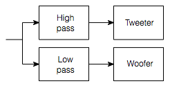
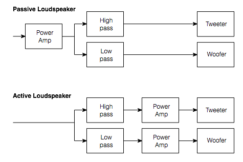
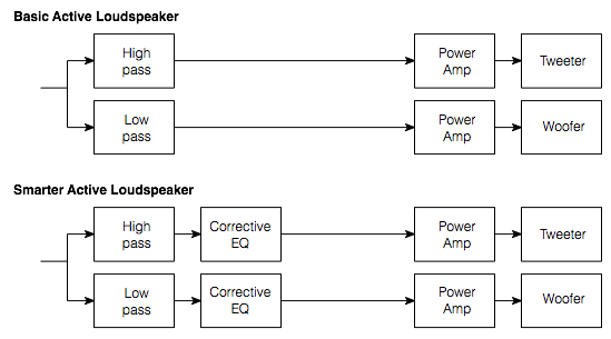
Let’s assume, for the purposes of this article, that we’re talking about #3. So, let’s start by talking about how a system like that would work. The simple version is that you take an audio input, send it to two different filters, one called a “high pass filter” which lets the high frequencies pass through it and it makes the lower frequencies quieter. The second filter is called a “low pass filter” – you can figure that one out. The output of the high pass filter is sent to your “main” loudspeaker, and the output of the low pass filter is sent to the subwoofer.


Simple bass management algorithm
Fig 1. Simple bass management algorithm for one audio channel


That’s what happens if you have a good ol’ fashioned monophonic system with only one audio channel, one main loudspeaker and one subwoofer. Most people nowadays, however, have more than one main loudspeaker and lots of channels coming out of their players. So, in cases like that, we have to take the low end (the bass) out of each of the main channels using low pass filters, add the results all together, add the LFE channel to that, and send the total to the subwoofer. A simple version (with some important details left out, since we’re only talking about basic concepts here…) is shown in the diagram below.


Simple bass management system for a 5.1 system
Fig 2. Simple bass management system for a 5.1 system


Basics of Signal Addition

Let’s take an audio signal and add it to another audio signal – and, just to keep things simple, we’ll make them both sine waves. This is done by looking at the amplitude of the two signals at a given moment in time, adding those two values, and you get a result. For example:

The bottom plot is the result of adding the signals shown in the top and middle plots, moment by moment in time. For example, the red stars show the values at one moment in time. One plus one (the top two plots) equals two (the bottom plot).
Fig 3. The bottom plot is the result of adding the signals shown in the top and middle plots, moment by moment in time. For example, the red stars show the values at one moment in time. One plus one (the top two plots) equals two (the bottom plot).


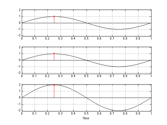
If you take a look at the example above, there are a couple of things that you can see. The first is that, if you add two sine waves, you get a sine wave. Also, if you add two sine waves of the same frequency, you get a sine wave of the same frequency. Next, if the two sine waves have the same amplitude and are “in phase”- basically meaning that they have the same value at the same time (sort of, but not really like a delay difference of 0) – the result is a sine wave that is in phase with the other two with double the amplitude of the two inputs.

Now, let’s move one of the two signals in time. We’ll make it late by half the length of the sine wave (in time) and see what happens.

The bottom plot is the result of adding the signals shown in the top and middle plots, moment by moment in time. For example, the red stars show the values at one moment in time. One plus one (the top two plots) equals two (the bottom plot).
Fig 4. The bottom plot is the result of adding the signals shown in the top and middle plots, moment by moment in time. For example, the red stars show the values at one moment in time. One plus one (the top two plots) equals two (the bottom plot).

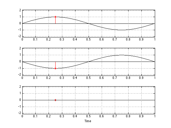
Now you can see that, since the bottom plot is the negative of the top plot at any given moment in time (because we’ve delayed it by half a “wave”), when you add them together, you get no output.

Let’s look at one last example, where the two input signals have some phase difference that is not quite so simple. This is shown in the figure below.

The bottom plot is the result of adding the signals shown in the top and middle plots, moment by moment in time. For example, the red stars show the values at one moment in time. One plus one (the top two plots) equals two (the bottom plot).
Fig 5. The bottom plot is the result of adding the signals shown in the top and middle plots, moment by moment in time. For example, the red stars show the values at one moment in time. One plus one (the top two plots) equals two (the bottom plot).

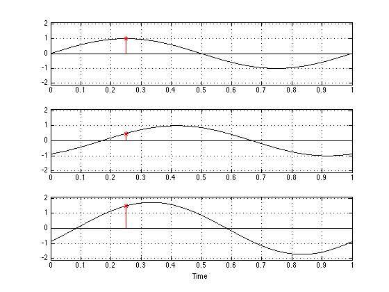
Again, you can see that, when you add two sine waves of the same frequency, you get another sine wave of the same frequency. You can also see that the phase (remember – phase is something like delay) of the result is not the same as the phase of either of the two inputs. Finally, you can see that the amplitude (the maximum value) of the result is neither 0 nor 2 – it’s something in between.

So, the moral of this story is that, if you have two sine waves then the result (what you hear) is (at least partly) dependent on how the two signals add – and that result might mean that you get something twice as loud as either input – or it could mean that you get nothing – or you get something in between.


 The real world

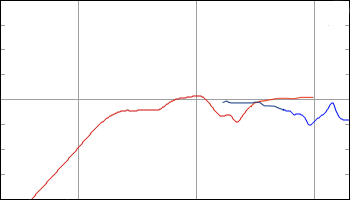
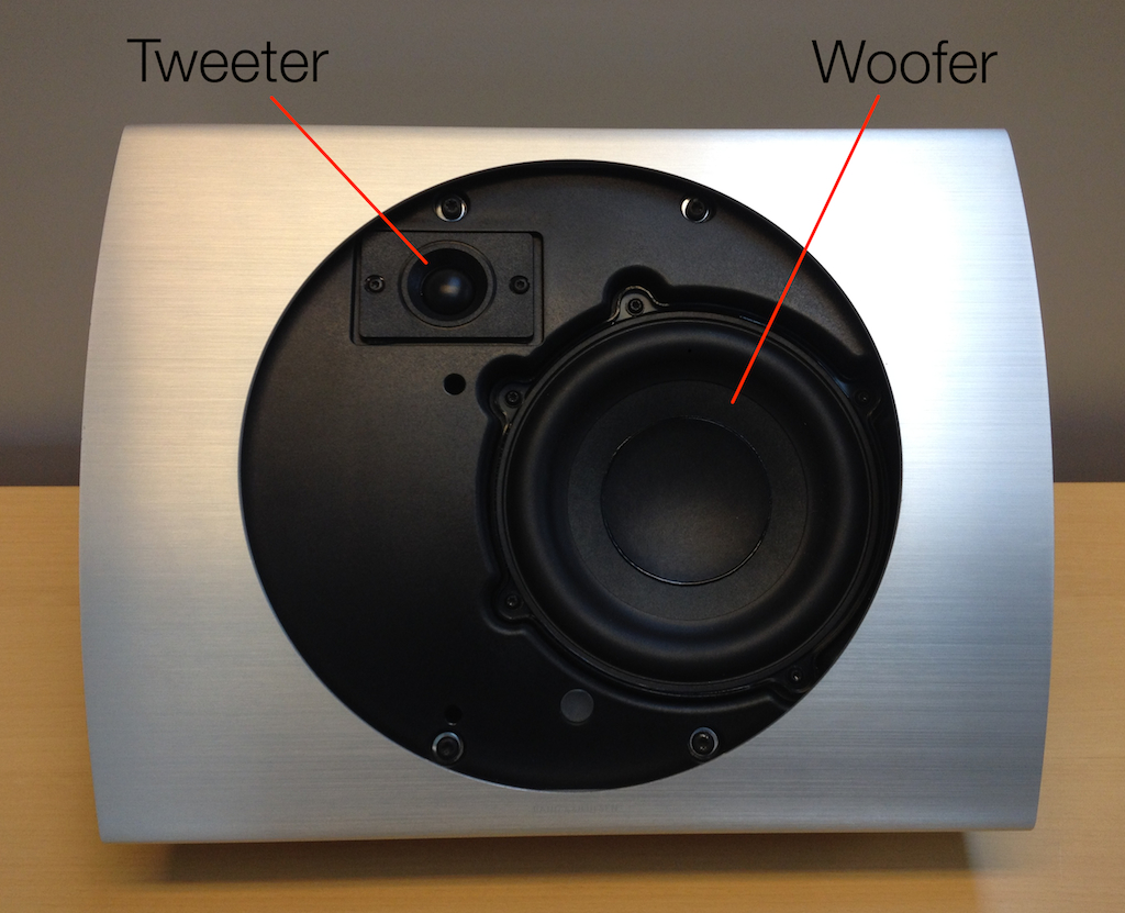
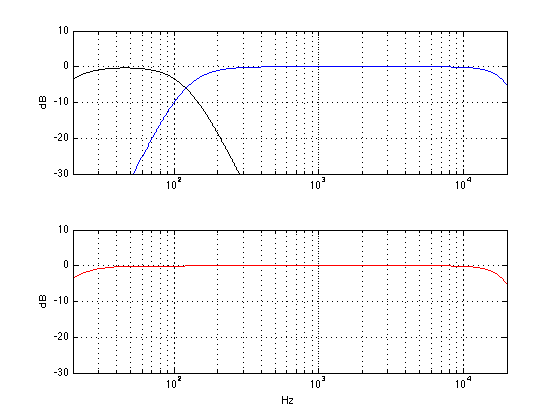
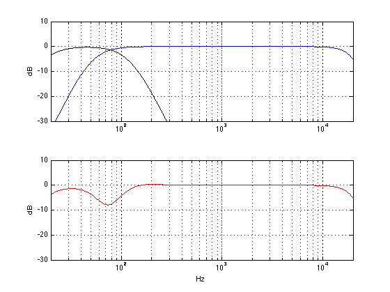
The three plots shown above illustrate some simple examples of what happens when you have two sound sources that are added together to produce a result. For the purposes of this article, the two sources are two loudspeakers – the “main” loudspeaker and the subwoofer, and the result is the sum of those two signals at your listening position. Let’s go back to thinking about what frequency ranges are produced by these two loudspeakers. The plot below shows the magnitude responses of the filters in a BeoVision 11’s internal bass management system at its default crossover frequency of 120 Hz. The red curve shows the response of the low pass filter whose output is sent to the subwoofer output. The black curve shows the response of the high pass filter whose output is sent to a main loudspeaker.

The magnitude responses of the filters in a BeoVision 11's bass management system.
Fig 6. The magnitude responses of the filters in a BeoVision 11’s bass management system.

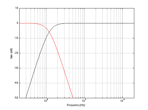
Take a look at the response of the signal that is processed by the low pass filter. You’ll notice that, although the “crossover frequency” is set to 120 Hz, there is still signal coming out of the filter (and therefore out of the subwoofer) above that frequency – it’s just getting quieter as you go further up and away from the crossover.

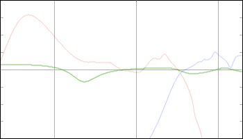
You might also notice that, at the crossover frequency, the level of the signal coming out of the low pass filter is identical to the level of the signal coming out of the high pass signal. That’s (more or less) what makes it the crossover frequency. As you move down from that frequency, you gradually get more out of the low pass (the sub) than the high pass (the main). As you move up in frequency, the opposite happens. However, there is a region around the crossover where both loudspeakers are contributing roughly equally (within reason) to the signal that you get at the listening position. So, the “truth” is a little more like the plot below:

A conceptual way of thinking about which loudspeaker is playing the audio signal.
Fig 7. A conceptual way of thinking about which loudspeaker is playing the audio signal.

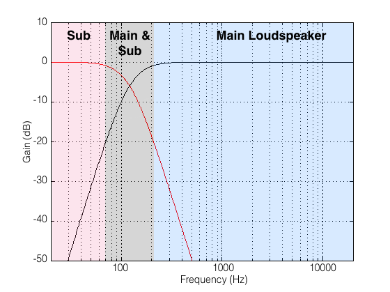
I’ve chosen -20 dB as the point where I can start ignoring a signal, but that’s a pretty arbitrary decision on my part. I could have set my threshold higher or lower and still argued that I was right. So, if you disagree with my choice of -20 dB as the threshold of “I don’t care any more” then I agree with you. :-)

By now, you should start to worry a little. You should be asking something like “hmmmm… you’re telling me that there is a big band of frequencies (say, roughly between 1 and 2 octaves) right around where human voice fundamental frequencies sit (well, at least my voice sits there – but I sing bass…) where a bass management system will send the signal out of two loudspeakers!? AND, to add insult to injury, you told me (in the previous section) that if the phases and amplitudes of those signals from those loudspeakers aren’t perfectly aligned, the result at the listening position won’t be the same as the input of the whole system?” If you ARE asking something like that, then you’re in good shape. As has been said by many other people in the past: the first step in fixing a problem is admitting you have one.

So, let’s ask a different question: what parts of the audio signal chain could affect either the amplitude or the phase of the signals coming out of the loudspeakers? Brace yourself… This list includes, but is not exclusive to:

  1. The characteristics of the filters in the bass management system
  2. The characteristics of the filtering in the loudspeakers
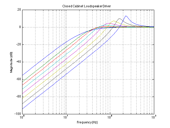
  3. The physical principal of the loudspeaker (i.e. sealed cabinets will be different from ported loudspeakers which are different from passive radiators)
  4. Diffraction (although this might be a small issue)
  5. Latencies (total delay) of the loudspeakers (for example, digital loudspeakers have a bigger delay than analogue ones typically)
  6. Distances of the loudspeakers to the listening position
  7. The characteristics of the room itself
  8. And more!

All of these issues (including the ones that fall under the “And more” category) have some effect on the phase (and amplitude) of the signal that you hear at the listening position. And, since some of these (like the distances and the room characteristics) are impossible for us (as a manufacturer) to predict, we have to give you, the end user, some way of adjusting your signals so that you can compensate for misbehaviour in your final system.

Now, although this is a “technical” article, I think that it would be too technical to start looking at the specifics of the phase responses of sealed cabinet vs ported loudspeakers, for example, since the details will be messed up by the listening room anyway. So, instead of getting into too many details, let’s just say that “you can’t expect your system to work perfectly without tweaking it” (see the reasons above) and just talk about some strategies for setting up your system so that it behaves as well as it can (without going out and hiring an acoustical consultant).
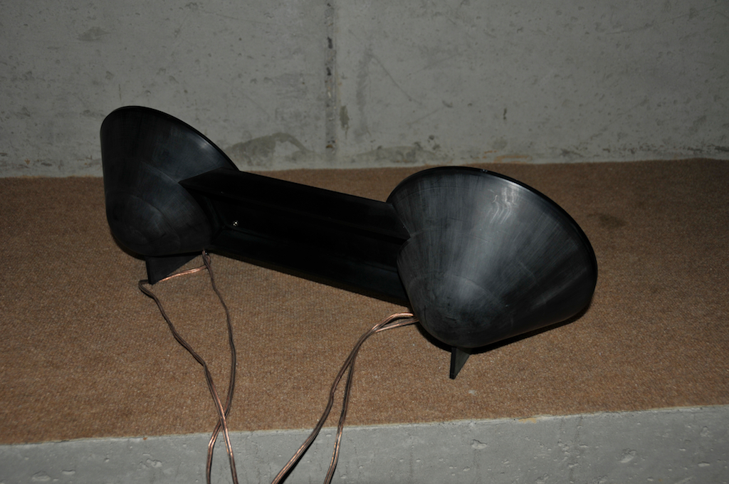
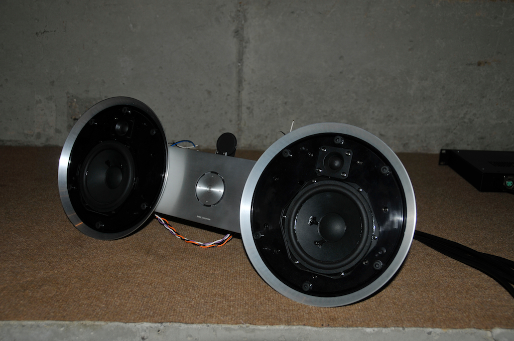
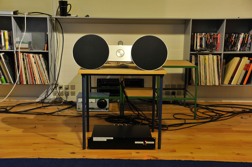
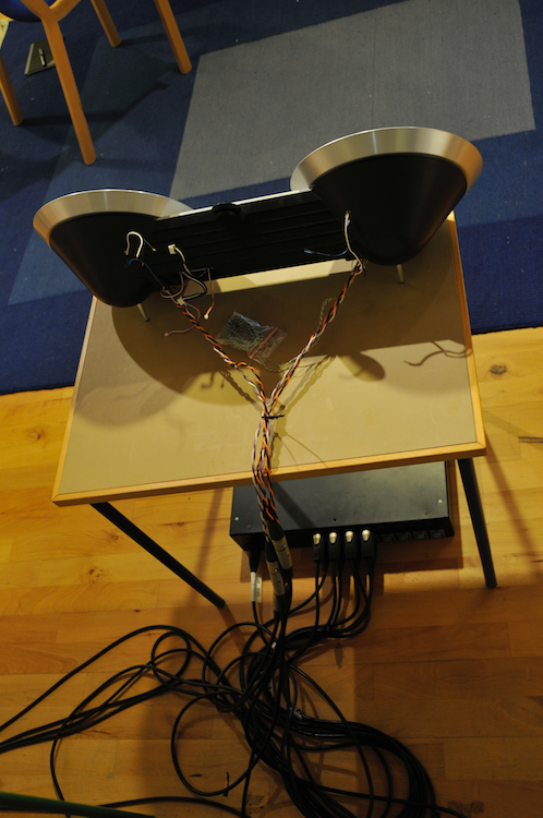
BeoLab 19 Controls

The BeoLab 19 has a number of controls that have not been available on previous B&O subwoofers. As a result they may cause a little confusion and playing with them without knowing what to expect or listen for could result in your system not performing as well as it could. On the other hand, it could be that these controls could help you improve your system if you’re finding that it’s not really behaving.  Let’s take each control, one by one, and explain what it does, and talk about strategy afterwards.

BeoLab 19's control panel
Fig 8. BeoLab 19’s control panel

Gain

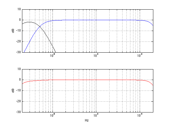
The gain knob (on the left in the diagram above) is basically just a volume knob that controls how loud the subwoofer is overall. Let’s say, for example, that you have a perfectly configured system, then the outputs of the subwoofer and the main loudspeaker mate perfectly and result in a perfectly flat response below, through and above the crossover region. (this never happens in real life – but we can pretend). The diagram below shows an example of this, where the top plot shows the outputs of the subwoofer and main loudspeaker and the bottom plot shows the total result at the listening position.

The output of a subwoofer and a main loudspeaker, with a "correct" crossover, at the same distance, with the same gain, with no room acoustics to bother anyone...
Fig 9. The output of a subwoofer and a main loudspeaker, with a “correct” crossover, at the same distance, with the same gain, with no room acoustics to bother anyone…

If you do nothing but change the gain of the subwoofer, (using the Gain knob on the BeoLab 19, for example) then the result would be something like the plot below.

The output of a subwoofer and a main loudspeaker. The subwoofer's gain has been increased by 6 dB. The distance to both loudspeakers is the same.
Fig 10. The output of a subwoofer and a main loudspeaker. The subwoofer’s gain has been increased by 6 dB. The distance to both loudspeakers is the same.

You can see in the plot above that all you do is to boost a region of low frequencies without doing anything strange through the crossover region. So, if you like bass, this might be a nice tweak for you. However, in theory, your goal is to get a response like the one in the first plot, where the outputs of the subwoofer and main loudspeakers have the same level (at the listening position).

LP Filter

One possible configuration of the BeoLab 19 is to connect it in parallel with your main loudspeakers and to not use and external bass management system.

A block diagram of the parallel method of connecting a subwoofer to a 2-channel stereo system.
Fig 11. A block diagram of the parallel method of connecting a subwoofer to a 2-channel stereo system.

If you do this, then you are relying on the fact that the main loudspeakers have a high pass filter built-in, and you will align the low pass filter inside the BeoLab 19 to have approximately the same frequency so that the total result is a smooth-ish crossover region. In order for the low pass filter to work, you will have to turn it ON using the switch. (Note that, if you’re using an external bass management system as in the BeoVision 11, for example, then you should turn the low pass filter OFF, thus removing it from the signal path of the subwoofer.)

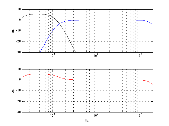
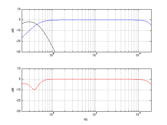
In theory, the goal here is to match the cutoff frequencies so the two loudspeakers behave nicely together across the crossover region. For example, if the natural low frequency cutoff is about 50 Hz, and you set the LPF in the subwoofer to 50 Hz, then you get the result below

The theoretical responses of a subwoofer with a low pass of 50 Hz (black curve) a main loudspeaker with a high pass of 50 Hz (blue) and the total sum at the listening position (red) in an imaginary world.
Fig. 12. The theoretical responses of a subwoofer with a low pass of 50 Hz (black curve) a main loudspeaker with a high pass of 50 Hz (blue) and the total sum at the listening position (red) in an imaginary world.

What would happen if you set the LPF incorrectly – let’s say that you make it higher than the correct value, since you would think that, by overlapping the sub with the main speaker, you’ll get more output and impress the neighbours. Well, the result would be the plot below.

The theoretical responses of a subwoofer with a low pass of 120 Hz (black curve) a main loudspeaker with a high pass of 50 Hz (blue) and the total sum at the listening position (red) in an imaginary world.
Fig 13. The theoretical responses of a subwoofer with a low pass of 120 Hz (black curve) a main loudspeaker with a high pass of 50 Hz (blue) and the total sum at the listening position (red) in an imaginary world.


As you can see, although the sub is now delivering more signal (because it’s going all the way up to 120 Hz instead of 50 Hz in the previous plot), you actually get a reduction in the total output of the system. This may be initially counterintuitive, but it’s true in our example, since (as you may remember from something I said earlier in this article) the phase of the subwoofer is, in part, determined by the characteristics of the filtering in the loudspeaker. By changing the low pass filter frequency, we change the phase of the subwoofer in the crossover region and result in a cancellation with the main loudspeaker instead of a summing. In essence, both the sub and the main loudspeaker are now working very hard to cancel each other (especially around 80 Hz or so) and you hear very little at the listening position.

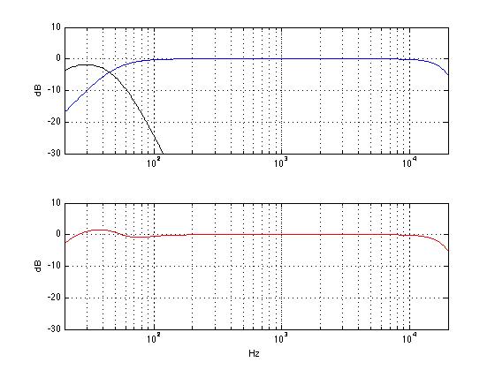
On the other hand, I have assumed here that the main loudspeaker’s high pass filter is a very specific type. A different main loudspeaker with a low frequency cutoff of 50 Hz would have had a completely different behaviour as you can see below.

The theoretical responses of a subwoofer with a low pass of 50 Hz (black curve) a different main loudspeaker with a high pass of 50 Hz (blue) and the total sum at the listening position (red) in an imaginary world.
Fig 14. The theoretical responses of a subwoofer with a low pass of 50 Hz (black curve) a different main loudspeaker with a high pass of 50 Hz (blue) and the total sum at the listening position (red) in an imaginary world. (Note that the slope of the high pass filter in the blue curve is different from Figures 12 and 13.)

So, the moral of the story here is that setting the low pass filter frequency will have some effect on your total response. However, you should not jump to the conclusion that you can predict what the frequency should be – you will have to fiddle with the knob whilst listening to or measuring the total output of the system. You should also not jump to the conclusion that increasing the frequency range that is covered by the subwoofer in a parallel configuration will result in more output from your system. Overlap is not necessarily a good thing – sometimes, more is less…

Phase

Go back up and take a look at the two sine wave in the plots in Figure 4. One way to describe these two waves is to say that the middle one is half a wave later than the upper one – in other words, they are 180º out of phase. Another way to describe them is to say that the middle one is the inverse of the upper one – they have the same instantaneous value at any time, except that they are the negative of each other (in other words, signal 2 = signal 1 * -1).

So, intuitively, you can see that shifting the phase of a signal by 180º is the same as flipping it upside down. This could mean that, for example, all other things being ignored, that when a kick drum tells your subwoofer to push outwards, shifting the phase by 180º will result in your subwoofer sucking inwards instead. However, this is only true if all other things are being ignored. As soon as your subwoofer has a high pass filter (i.e. a low frequency limit) and a low pass filter (a high frequency limit) and it’s a loudspeaker driver in a cabinet in a room, all bets are off. All of those aspects (and more!) will have some effect on the phase of the system, so you can’t predict whether the kick drum will cause the woofer to put out or suck inwards.

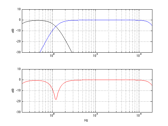
So, instead of worrying about the “absolute phase” of the subwoofer, it’s more interesting to worry, once again, how it matches up with the main loudspeaker. Let’s take exactly the same responses from the plots shown in Figure 14 above (which didn’t add together so well for some reason) and shift the phase of the sub by 180º using the Phase switch. The result is shown below in Figure 15.

The theoretical responses of a subwoofer with a low pass of 50 Hz (black curve) a different main loudspeaker with a high pass of 50 Hz (blue) and the total sum at the listening position (red) in an imaginary world. In this case, the subwoofer's polarity has been inverted by changing the "phase" switch to 180.
Fig 15. The theoretical responses of a subwoofer with a low pass of 50 Hz (black curve) a different main loudspeaker with a high pass of 50 Hz (blue) and the total sum at the listening position (red) in an imaginary world. These are the same as the loudspeakers shown in Figure 14, however, in this case, the subwoofer’s polarity has been inverted by changing the “phase” switch to 180.

As you can see, the big dip in the total response of the system (seen in Figure 14) has been corrected, and we now have more output (actually, a little too much) below that. So, the result is that the total system response is much better than it was without flipping the phase switch.

Of course, if we flipped the phase switch in a system that was behaving nicely, then bad things might happen. Let’s flip the phase on the system shown in Figure 9, for example. That total result would look like the one in Figure 16, below.

The theoretical responses of a subwoofer with a low pass of 120 Hz (black curve) a different main loudspeaker with a high pass of 120 Hz (blue) and the total sum at the listening position (red) in an imaginary world. In this case, the subwoofer's polarity has been inverted by changing the "phase" switch to 180.
Fig 16. The theoretical responses of a subwoofer with a low pass of 120 Hz (black curve) a different main loudspeaker with a high pass of 120 Hz (blue) and the total sum at the listening position (red) in an imaginary world. In this case, the subwoofer’s polarity has been inverted by changing the “phase” switch to 180.

As you can see, you get the same amount of low bass in Figures 9 and 16. However, there is a nasty dip at the crossover frequency of 120 Hz when the two loudspeakers are cancelling each other.

So, the moral of the story here is that, if you have a problem in the crossover region between the main loudspeaker and the subwoofer, flipping the phase of one of the two might help the situation – although it might make things worse…

Pos (aka Position)

Almost every loudspeaker in the Bang & Olufsen portfolio has a switch that lets you change the characteristics of the loudspeaker to compensate for the differences in its response as a result of its placement in a room. Generally speaking, the closer you put a loudspeaker to a wall, the more bass you’ll get out of it. If you put it closer to two walls (i.e. in a corner) you’ll get even more bass. However, that is a very general characterisation – the reality is that you’ll get a little more at some frequencies and a little less in other frequencies – and that behaviour is dependent on the diameters of the loudspeaker drivers, the crossover frequencies, and the  physical shape of the loudspeaker.

So, without getting into the details of exactly what is being changed in a BeoLab 19 (or BeoLab 2 or BeoLab 11 – or any other loudspeaker for that matter), let’s say that you should put the position switch in whatever setting best corresponds to the location of the loudspeaker in your room. However, if you want, you could cheat a little and fiddle with the switch to see if you like another setting more.

For example, if your loudspeaker is in the corner, and you put it in “free” mode, you’ll get LOTS of bass – too much bass. But if you like bass, this is one way to get it. Of course, there are other implications to this decision, but if you like bass enough, that might be reason enough to change to the “incorrect” the switch setting.

Wired / Wireless

The BeoLab 19 has the ability to receive its input via the analogue or digital input OR via the wireless receiver module that is built into it. This switch merely tells the loudspeaker whether it should “listen” to the wired input (either analogue or digital) or the wireless one. (Note that the BeoLab 2 and the BeoLab 11 do not have wireless receivers.)

L / R/ L+R

Most subwoofers (including the BeoLab 2 and the BeoLab 11) are built with the assumption that you will use them either:

  • as a stand-alone subwoofer in a multichannel (i.e. 5.1 or 7.1) system where it gets the “.1” output from the source (that may, or may not have bass management) and so you just send one audio channel into it OR
  • in a 2.1 setup where you want the left and right channels coming into the subwoofer where they are added together produce a mono bass signal internally

Consequently, most subwoofers either have 1 input (assuming that they are to be connected to the “subwoofer out” on something like an AVR) or a 2-channel stereo input (assuming that they should “see” left and right) that is summed to mono. BeoLab 2 and 11 are built based on the second assumption.

BeoLab 19 allows you to use the subwoofer in either of these configurations. So, in either “L” or “R” mode, it is only “listening to” the Left or Right audio channel on the Power Link input. In “L+R” mode, the input of the subwoofer is taking both audio input channels and summing them to make a mono input to the subwoofer. Note that, if you send exactly the same signal on the Left and Right audio channels on the Power Link cable, and then you switch the BeoLab 19 from either L or R to L+R, you’ll find that you get a doubling in the output level. This is because a signal plus itself is twice as loud. Since this is what BeoLab 2 and 11 do all the time, if you simply replace a BeoLab 2 or 11 with a BeoLab 19, you should put the 19 in “L+R” mode – otherwise you’ll lose some bass in your system.

However, if you want to use a single Power Link cable to run to the Subwoofer and to another loudspeaker (say, a centre channel, for example), then you should put the BeoLab 19 in either L or R mode (and the other loudspeaker in the opposite mode) so that you can access both loudspeakers independently. This is also the case if you want to run two BeoLab 19’s on the same Power Link cable and use the 2-channel LFE output option in a BeoVision 11. In this case, you se one BeoLab 19 to “L”, the other to “R” and set the Speaker Roles in the BeoVision 11 to “Sub Left” and “Sub Right” (or “Sub Front” and “Sub Back”) appropriately.

Note that, if you are in Wireless mode, the “L/R/L+R” switch does nothing.


How to do it (Finally!)

Method for an Externally Bass Managed Configuration

If your main loudspeakers and your subwoofer are connected to a system that has a bass management system, then you should use it. There are a number of reasons for this:

  • the main loudspeakers may behave better (for example, with respect to distortion or port noise) if they are not being pushed by a lot of bass
  • a bass management system will work for a multichannel loudspeaker system
  • a bass management system (for example, in a BeoVision 11) will be capable of making some “intelligent” decisions with respect to your entire system
  • a good bass management system (for example, in a BeoVision 11) will allow you to make fine adjustments to accommodate your configuration and room

So, your procedure here (assuming that you have a BeoVision 11 and a BeoLab 19 and some main loudspeakers) is as follows:

  1. Turn off the LP Filter on the BeoLab 19, set the Phase to 0, set the Gain to 0, and set the other switches to whatever is best for your particular configuration.
  2. Put the correct loudspeaker models into the Speaker Connections menu on the BV11.
    This will compensate for differences in the latencies and sensitivities of the loudspeakers, in addition to making some intelligent decisions about where to route the bass.
  3. Set your Speaker Distances correctly
    This will ensure that you do not have phase differences in the loudspeakers at the listening position as a result of problems caused by the speed of sound and mis-matched distances.
  4. Set your Speaker Levels correctly
    On a BeoVision 11, this is done by making sure that, at the same volume level, all loudspeakers produce the same level in “dB SPL, C-weighted, Slow” on an SPL meter like this one, or this one, or this one, for example.
  5. Turn on a piece of music that has a constant bass level
    The opening of Freddy Mercury’s “Living on my Own” or Santanta’s “You Are My Kind” are a possible tunes. Claire Martin singing “Black Coffee” is also a good candidate. If you want to look like a professional, then I suppose that you could use pink noise or this track instead of music.
  6. Sit in the listening position and listen to the total behaviour of the system. Pay particular attention to “unevenness in the bass”. In other words, listen to the bass and pay attention to whether some notes are quieter or louder than others.
  7. In theory, if you performed Step 4 correctly, then you shouldn’t have to play with the Speaker Level in the TV or the Gain on the subwoofer.
  8. If there is a general area somewhere in the middle of the bass where lots of notes are too quiet, try flipping the phase on the subwoofer.
  9. If some individual frequencies (or notes) are quiet then playing with the allpass filter on the TV might help.
  10. If some individual frequencies (or notes) are louder than others, this is probably caused by the room, and you might be able to deal with it by moving the subwoofer. If, when you put the sub in the corner, you make this problem worse, it is almost certainly the room acoustics that you’re dealing with, so moving the sub is your best bet.

Method for a Parallel Connection Configuration

Since, in a configuration where the sub and the loudspeaker are connected in parallel, the behaviour of the transition between the BL19 and the main loudspeakers (let’s say that there are only two of them for this example) in the system is not only dependent on the loudspeaker models themselves, but also the distances to the 3 loudspeakers and the behaviour of the room, the best thing to do is to do a bunch of acoustical measurements, interpret the results and then make adjustments to the system, evaluating the measurements repeatedly as you go along. If you can’t do this, then you can tune it by ear. Unfortunately, this will take more time, and might require an extra person to help, but it will probably result in better results than doing nothing. Here is how I would do it:
  1. Turn the LPF frequency as low as you can go
  2. Turn on a piece of music that has a constant bass level
  3. The opening of Freddy Mercury’s “Living on my Own” or Santanta’s “You Are My Kind” are a possible tunes. Claire Martin singing “Black Coffee” is also a good candidate. If you want to look like a professional, then I suppose that you could use pink noise or this track instead of music.
  4. Sit in the listening position and ask someone to turn the LPF as low as it will go.
    You should notice that there is a “hole” in the level of the bass between the subwoofer and the main loudspeaker. Turn up the LPF frequency and pay attention whether the “hole” fills up or gets worse. If it gets worse, flip the phase switch and start Step 4 again.
  5. If the hole did not get worse, then keep turning up the LPF frequency until it sounds like there the hole is filled up.
  6. One you’re done playing with the LPF frequency, try moving the Gain to adjust the bass to the level that you like.


 Addendum

Test Track: -20 dB FS sine tone in semitone steps from 250 Hz down to 10 Hz. 2-channel 128 kbps AAC file

There are some more examples of what happens when you play with the various knobs on a subwoofer here.

B&O Tech: What is Sound Design?

#7 in a series of articles about the technology behind Bang & Olufsen loudspeakers


My official job title at Bang & Olufsen is “Tonmeister and Technology Specialist in Sound Design”. The second half of that title is a bit weird – what is a “sound designer” and why would B&O want to have one on staff?

To answer that question, let’s start by talking about how a loudspeaker behaves in a real room. In many respects, a loudspeaker is like a lamp. Turn on a lamp and look at where the light goes. Some of it goes directly on what you want to look at – like the book you’re trying to read, for example. More of the light goes in other directions – it radiates outwards and reflects off of the walls, floor, ceiling, and furniture. And, if your lamp is anything like the one in my living room, then the light that shines directly on your book is not the most important part. In fact, if there was no direct light shining on the book, you would probably still be able to read your book because of the light reflecting towards your book off of everything else in the room.

A loudspeaker is basically the same thing – you have some sound that radiates directly out of the loudspeaker towards the listening position (assuming that the loudspeaker is “aimed” at the listening position) like a laser beam (like the light shining directly on your book – this is called the loudspeaker’s “on-axis magnitude response” or the “frequency response“). In addition to this, you have the sound that radiates outwards in all directions simultaneously like a big ball expanding in all three dimensions (this is called the “power response” of the loudspeaker). There are a couple of things to think about here. The first is that the sound that is coming directly from the loudspeaker to the listening position isn’t necessarily in the direction that the people who built the loudspeaker would call “on-axis” – in fact, more than likely, it’s slightly off-axis. This is okay, since you can think of a loudspeaker’s principal axis of radiation more like the beam from a flashlight than a laser beam (so you have a “listening window” instead of a single spot). The second thing to remember is that, in most listening situations, you are hearing FAR more energy from the loudspeaker’s total power response than you do from the direct sound’s magnitude response. In fact, in a lot of situations, you don’t have any direct sound at all – just power response filling up the room and reflected back to you. (If you’d like to learn more about this concept, read this posting to start off.)

The (rather important) moral of this short story is that the power response is at least as important as the magnitude response – and usually much more important. The problem is that, if you read loudspeaker reviews in magazines, you get the impression that the on-axis magnitude response is the most important thing there is to know about a loudspeaker. This is simply not true – the on-axis response of a loudspeaker is one of the easier things to measure, so that’s what gets measured by most people. It’s very difficult to do a reliable power response measurement, so most people don’t do one. Keep this in mind as you keep reading.

So, what are the steps we take when we tune our loudspeakers during the development process?

Step #1: Measurements

Prototype #3 on the crane in the Cube. The microphone is visible in the distance. It's at the end of a slender tube held in place by a white pyramid.

The prototype is put on the crane in the Cube and the linear part of its acoustic response is measured by the acoustical engineer assigned to the project. The output from these measurements consists of four final measurements:

  1. the on-axis frequency response
  2. the frequency response of the loudspeaker at a lot of different angles in all directions (not just around the loudspeaker’s “equator” but also above and below it)
  3. a kind of an average response in a “listening window”
  4. the power response (made by adding the results of all the measurements done in all directions)

Since we make DSP-based active loudspeakers (unlike passive loudspeakers) the angular direction that is chosen as the “on-axis” location is arbitrary. This is because the final response from each loudspeaker driver and the delays that are used to time-align them are determined by the filtering that we apply in the DSP. I’ll talk about this in a future posting. However, what this means is that “on-axis” is “wherever we decide it to be” – NOT “directly in front of the tweeter” or “directly in front of the loudspeaker”. So, we do a measurement of the frequency response (which is comprised of the magnitude response and the phase response) of the loudspeaker in the absence of any wall reflections at some distance, on a line that has been determined to be the “on-axis” direction.

An example of the "on-axis" direction.
An example of the “on-axis” direction. Note that this is not necessarily the actual on-axis direction for the BeoSound 8 – it’s merely an artist’s conception of the idea of “on-axis”.

The power response of a loudspeaker is kind-of-sort-of the sum of its magnitude responses in all directions. This is essentially a measure of the total acoustic energy that a loudspeaker sends into a room in all directions at the same time. So, instead of thinking of a loudspeaker as a laser beam (as in the on-axis response), this considers the loudspeaker as a naked light bulb, sending sound everywhere (which is actually a little closer to the truth).

My attempt to represent the power response - a sphere of sound that radiates in all directions in 3D space from the loudspeaker.
My attempt to represent the power response – a sphere of sound that radiates in all directions in 3D space from the loudspeaker.


The listening window is an area that has the on-axis line as its centre. It’s an oval-shaped area that is wider than it is high, that represents an area in front of the loudspeaker where we think that this listeners will typically be located.


The "Listening Window". Note that it's wider than it is high, and that its centre is the "on-axis" direction.
The “Listening Window”. Note that it’s wider than it is high, and that its centre is the “on-axis” direction.


In the old days (actually, for all of the active loudspeakers before BeoSound 8), the result of this process would have been two filters. The first would be a correction filter made by the acoustical engineer that made the loudspeaker’s on-axis frequency response flat in its magnitude response. The second would have made the power response smooth (i.e. without too many dips and bumps). Then the loudspeaker would have gone into the listening room, with those two filters as two different options as starting points for the listening-based sound tuning.

Nowadays, we do things a little differently, the measurements that are performed in the listening window (between 10 and 20 measurements in total) are compared and analysed for common aspects in their time responses. In other words, we’re checking to see whether the loudspeaker has natural resonances in it that causes it to “ring” in time (just like a bell rings when you hit it). Ringing is a natural behaviour of a loudspeaker, but that doesn’t mean it’s a good thing – it means that some frequency (the one that’s ringing) lasts longer than the others when you hit the loudspeaker with a signal (usually it’s ringing at lots of different frequencies). Depending on what frequencies are ringing, the result could be a “muddy”- or a “harsh”-sounding loudspeaker (to name just two of many descriptors meaning “bad”…) If we can see the same ringing in all (or at least most) of the measurements in the listening window, then the DSP engineer working on the project will make a filter for the signal processing that makes the ringing go away – in essence, we make the signal that we’re sending into the loudspeaker ring opposite to the natural ringing of the loudspeaker itself. You can think of it like kicking your legs in the wrong direction when you’re on a swing to make yourself slow down – you’re actively working in the opposite direction of the natural resonance of the system (where you-on-the-swing is “the system”).

In addition to making the resonances go away, we add filters to

  • push  the low frequency response to go as low as we want it to
  • ensure that the loudspeaker drivers (for example, the woofer and the tweeter) meet each other correctly through the crossover and work together instead of against each other. In order to do this correctly, you can’t just build a crossover – you have to incorporate the natural frequency responses of the loudspeaker drivers as part of the total filter design.
How NOT to make a crossover filter. Although this filter will ensure that only the low frequencies go to the woofer and the highs to the tweeter, there is no compensation here for the natural behaviours of the loudspeaker drivers themselves. In other words, these curves should be the target for the crossover filter PLUS the drivers - not just the filter itself.
How NOT to make a crossover filter. Although this filter will ensure that only the low frequencies go to the woofer and the highs to the tweeter, there is no compensation here for the natural behaviours of the loudspeaker drivers themselves. In other words, these curves should be the target for the crossover filter PLUS the drivers – not just the filter itself.


An example of the natural on-axis magnitude responses of the woofer and tweeter in a two-way loudspeaker system like a BeoSound 8. The red curve shows the natural response of the woofer, the blue curve shows the response of the tweeter.
An example of the natural on-axis magnitude responses of the woofer and tweeter in a two-way loudspeaker system. The red curve shows the natural response of the woofer, the blue curve shows the response of the tweeter. In other words, this would be the magnitude responses of the loudspeaker drivers if we didn’t do any filtering. Note that distinct lack of bass and the peaky thing in the high end…


At the end of this process, we have a loudspeaker that has a final response that has been corrected so that it measures well inside the listening window. We also have a bunch of measurements that we’ll probably come back to later.

An example of the correction curves used to "fix" the responses of the loudspeaker drivers with the natural responses shown in the previous figure. This is the kind of filter that would be implemented in the DSP by the acoustical and the DSP engineers based on the measurements.
An example of the correction curves used to “fix” the responses of the loudspeaker drivers with the natural responses shown in the previous figure. This is the kind of filter that would be implemented in the DSP by the acoustical and the DSP engineers based on the measurements. If you look carefully, you can see that many of the aspects of this curve are simply the measurements of the natural response flipped upside down. You’ll also notice that the slopes of the crossover are not as pretty as the ones shown above, since they correct for the drivers’ characteristics as well.


Step #2: Tuning

The prototype with its correction filters are brought into the listening room and we start playing music through it. The first thing to do is just sit and listen using recordings that we know really well (usually, for me, that means starting with “Bird on a Wire” by Jennifer Warnes from Famous Blue Raincoat  – I’d guess that I have heard that song, on average, once a day, every day, since about 1990 or so). Pretty soon, some problem will be apparent. Depending on the problem that shows up, we’ll try to fix it by correcting the physical reason for the problem. (This is done by the acoustical engineer working with the mechanical engineers to sort out where the problem occurs and how to fix it.) For example, if a part of the loudspeaker cabinet is vibrating and “singing along” with the loudspeaker, we’ll stiffen the cabinet, either by increasing its thickness, or changing the material it’s made out of, or adding ribs or bulkheads or some combination of those things. Once that problem is fixed, we bring it back into the listening room, find another problem, fix it, listen, complain, fix, listen, complain, fix, rinse, repeat, etc. etc…

Eventually, once all of the problems that we can fix with physical corrections are done, we start the next phase of the tuning. This is where the “design” part of the sound design comes in…

We set up the loudspeaker with its correction filters and its physical improvements in the listening room and start listening to music again. Now, if something sticks out as sounding wrong in the recording, we use an equaliser to correct it. If a note is sticking out that shouldn’t be, then we put in a dip in the equalisation to reduce the problem. If there’s some frequency band that seems to be missing, then we’ll use an equaliser to boost it a little to get it back. Typically, that process takes about 3 to 5 days in the listening room, and at the end, we have something between 20 and 40 extra equalisers in the signal flow. When that’s done, we pack up and go to a different listening room and start the process from scratch again. A couple of days later, we have another 20 – 40 filters. Then we pack up and go to a different room and start again. That process is done in something like 4 or 5 rooms, depending on the loudspeaker that we’re working on. Usually, we try to use rooms that are different from reach other, but also that will be representative of the acoustic behaviours of the rooms that the products will be used in. For example, when we were tuning the BeoPlay A9, one of the “rooms” was outdoors in the acoustical engineer’s back yard. This was because some customers will put their A9 out on the back deck or by the pool – so we used that situation as one of our tuning rooms.

So, now we have 4 or 5 sets of tunings, each with about 30 equalisers in them (give or take…). These tunings are then analysed to see what is common amongst them. You see, if we were to just tune a loudspeaker in a single position in a single room, a big part of the tuning would be there to correct the acoustical behaviour of the room. For example, in our main listening room in Struer, we have a pretty nasty room mode that rings at about 55 Hz. Whenever I tune a loudspeaker in that room, I put in a notch filter at 55 Hz to reduce the audibility of the problem (especially since I start tuning using Bird on a Wire, and it’s in A Major, and 55 Hz is an A). However, if your living room is not the same size as Listening Room 1 in Struer, then your room modes will be at different frequencies, so you should have a notch filter at those frequencies instead of 55 Hz. So, in order to eliminate the individual corrections for the individual rooms that we used for tuning the loudspeaker, we just take the common aspects from each tuning. For example, if the first tuning has a dip at 55 Hz and a boost at 200 Hz, and the second tuning has a dip at 65 Hz and a boost at 200 Hz – we only keep the 200 Hz boost (since the notches at 55  Hz and 65 Hz are probably due to the rooms, not the loudspeaker itself).

Once the common aspects of all those tunings have been extracted, we use those to build an equalisation that is, essentially, the sound design. That equalisation is built into the loudspeaker, and we start getting more people to listen to it in more rooms (for example, we’ll send people home with prototypes that include the sound design tuning to get “real world” testing).

The green curve shows the additional equalisation added in the sound design process. This is applied to the loudspeaker in addition to the engineering-based filters shown by the red and blue curves.
The green curve shows an example of the additional equalisation added in the sound design process. This is applied to the loudspeaker in addition to the engineering-based filters shown by the red and blue curves.


Why do you need Sound Design?

Of course, there are purists amongst you who will ask why it is that we need the sound design process in the first place. The logic goes that if you make a loudspeaker with a razor-flat on-axis frequency response, then you will get a perfect loudspeaker – end of story. Anything that is done afterwards to muck about with that response is just ruining the loudspeaker. Ignoring a lot of details, this would be true if you used your loudspeaker in a room that had no reflections – in other words, if all you hear is the on-axis sound, and all of that energy that goes in all other directions never reflects off of anything else and bounces back at you, then a flat on-axis response would probably be a good idea.

However, think back to where we started. We said that the power response of the loudspeaker is at least as, if not more, important than the on-axis magnitude response. This means that the sound that radiates away from the loudspeaker in directions other than yours is what you hear most of the time. The relationship between the on-axis magnitude response and the power response is determined by the physical shape of the loudspeaker and its components (as well as the frequencies of the crossovers). And, how that balance between the on-axis response and the power response is perceived at the listening position (wherever that might be…) is really unpredictable. So, rather than building a tuning that is based on a prediction, we experience it instead – by playing the loudspeaker in different rooms and different positions and assembling some sort of average behaviour in the real world.

One of the statements I’ve made on Bang & Olufsen marketing materials in the past (like this video, for example) is that, when you sit in your living room and listen to a pair of B&O loudspeakers, you should hear what the mastering engineer (or the mixing engineer, or the recording engineer) heard when he or she did the recording using professional studio monitor loudspeakers in a mastering or recording studio. (Note that this is very different from the philosophy that you should be able to sit in your living room, close your eyes, and be fooled into thinking that the musicians are standing in front of you. In my opinion this is a silly philosophy, akin to believing that you should go to a movie theatre and believe that you’re in the movie instead of watching it. A music recording should be better than real life – not the same as it. And, please – before you write a comment below telling me that I’m wrong, read this first – then this – and then come back and write a comment below telling me that I’m wrong.) However, since your living room is not a mastering studio, it doesn’t make sense for you to use studio monitors. In other words, the goal is that the combination of B&O loudspeakers and your living room should be the same as studio monitors and a recording studio.

So, the moral of the story is that the goal of sound design (at least at Bang & Olufsen…) is to ensure that our loudspeakers in a normal room (whatever that means for a given product) sounds like professional studio monitors in a recording studio. In other words, if we started making studio monitors instead of home loudspeakers, I’d be out of a job, since we wouldn’t need a sound design procedure to “undo” the effect the room has on our loudspeakers…


P.S

One thing that I did not talk about here (mostly just to keep things clear) was the off-axis responses of the loudspeaker, the collection of which comprises its directivity. That discussion will be left for a future posting.


P.P.S.

There is one aspect of this article that can explain one issue that some people have with B&O loudspeakers. If you take a look at some magazine reviews and some comments from people-who-post-opinions-about-loudspeakers-late-at-night-on-Internet-fora, they’ll say that our loudspeakers are obviously not worth anything, since they do not have a flat on-axis frequency response. Of course, if the only criterion you use to define what makes a loudspeaker “good” is a one-dimensional measurement at a single point in space, then you might be inclined to agree with that opinion.

However, if, like me, you live in three dimensional space in a house that has walls, floors and ceilings – and you have more than one chair and possibly even a friend or two – you might be inclined to think differently…

B&O Tech: What are subwoofers REALLY for?

#6 in a series of articles about the technology behind Bang & Olufsen loudspeakers


The Setup

Back in a previous posting, I said something that could be perceived as interesting… The short version of what I said there was that, if you’re making a DSP-based active loudspeaker (like all of the new loudspeakers in the B&O portfolio), you can essentially make it sound like whatever you want. You do this by adding filters in the digital signal processing (DSP). (Let’s assume for this article that we’re only talking about the on-axis magnitude response of the loudspeaker, and we’re working in an anechoic environment (aka a “free field” situation), since that will keep things simple.) This means that, if I can apply enough boosts and cuts, I can get any magnitude response I want out of the loudspeaker. In other words, I can have a 1″ tweeter that plays with a perfectly flat response from 20 Hz to 20 kHz.

However, there are some serious restrictions on this statement. As a minor example, if there is a problem with diffraction the only way to change that is to modify the shape of the loudspeaker cabinet (if you don’t know what diffraction is, don’t worry – it will not be mentioned again in this article).

However, there is one GIANT restriction on the statement that we’ll look at this week. This is a question of how loudly you want to play. So let’s look at that.

In order to make sound, a loudspeaker driver has to move in and out – this pushes and pulls the air molecules in front of it, creating small areas of higher pressure and lower pressure (relative to today’s natural barometric pressure) that radiate outwards, away from the driver. Those variations in pressure push and pull your eardrum in and out of your head which, in turn cause stuff to happen in your inner ear which, in turn causes stuff to happen in your brain – but that is all outside the scope of this discussion.

Back to the loudspeaker – it has to move in and out. The louder you want to play (more accurately, the higher the Sound Pressure Level (SPL), the more it has to move in and out. Also, the lower in frequency you want to play, he more it has to move in and out (to keep the same SPL).

The red arrow shows the direction of movement of the loudspeaker driver required to make a positive (or high) pressure. The driver has to go the other way (into the cabinet) to make a negative (low) pressure.


The real problem is the second of these, since the rule of thumb is that, every time you go down one octave (in other words, you divide the frequency by 2) you need to quadruple the excursion of the driver (the amount it moves in and out).

Let’s look at an example. The figure below illustrates the excursion required for different sizes of loudspeaker drivers in order to create a sound pressure level of 60 dB SPL (which is not very loud – but is a typical sort of listening level) at 1 m (which is a good approximation for how loud it will be all over your living room due to something called the room’s “critical distance” – we’ll talk about that in the future).

Notice that, for the 15″ woofer, it only has to move 0.08 mm out of the box (and 0.08 mm into the box) to produce a 20 Hz signal at 60 dB SPL. This is not very much movement. By comparison, the 4″ woofer has to move 1.2 mm which is much more than 0.08 mm, but still not much.

To bring this into the real world, this means that a woofer taken out of a BeoLab 3 (which is 4″ in diameter) would have to move 14 times farther than a woofer from a BeoLab 5 (15″ woofer) to produce the same output. This is because the 4″ woofer is smaller than the 15″, so to move the same number of air molecules, we have to move it more. (actually, what we’re really thinking about here is how many litres of air we’re moving, but that might be too much detail…)


The excursion of a driver (of different diameters) required to generate a signal of 60 dB SPL at 1 m from the front of the driver. Note that this assumes that your driver is mounted in a hole in the wall, not a real loudspeaker box (see text for the implications of this).


Let’s consider the practical implications of this graph. Since a BeoLab 3 woofer can move 1.2 mm in and out (and, of course, a BeoLab 5 woofer can move 0.08 mm). Both loudspeakers are able to produce a 20 Hz tone at 60 dB SPL. Therefore, if we choose to do so, we can make both loudspeakers have a magnitude response that was flat from 20 Hz to 20 kHz at this listening level (or quieter).

Let’s turn up the volume knob. We’ll go up to 80 dB SPL which is a bit loud, but certainly not enough to get the party going… Now we need to move the 15″ woofer 0.8 mm (still not very much…) and the 4″ woofer 11.6 mm to produce 20 Hz at 80 dB SPL. Of course, the BeoLab 5 woofer can easily move 0.8 mm, but 11.6 mm is too far to go for the BeoLab 3 woofer. So, if we didn’t have ABL to protect things from moving too far, we would not be able to tune the BeoLab 3 to be flat down to 20 Hz – we would have to “roll off” the low frequencies so that 20 Hz was not as loud as the frequencies above 20 Hz in order to prevent it from causing the woofer to move to far when you turn up the volume. (For example, we could tune it to be flat down to 40 Hz instead of all the way to 20 Hz.)


80dBspl
The excursion of a driver (of different diameters) required to generate a signal of 80 dB SPL at 1 m from the front of the driver. Note that this assumes that your driver is mounted in a hole in the wall, not a real loudspeaker box (see text for the implications of this).


Let’s go further, just to make things really obvious. We’ll turn up the volume to 110 dB SPL (which is very loud). Now, to get a 20 Hz tone out at this level, the 15″ driver will have to move 2.6 cm and the BeoLab 3 woofer would have to move 36.6 cm (which is silly). So, here it is obvious that, if we want to build the BeoLab 3 to play 110 dB SPL, we will have to use ABL or limit its low frequency content (or use some balance of those two things – a little ABL and a little higher low-frequency limit).


110dBspl
The excursion of a driver (of different diameters) required to generate a signal of 110 dB SPL at 1 m from the front of the driver. Note that this assumes that your driver is mounted in a hole in the wall, not a real loudspeaker box (see text for the implications of this).


Let’s look at this in another, more intuitive way. If we wanted a BeoLab 3 woofer to play as loudly as a BeoLab 5 woofer can play, at its peak excursion in and out of the cabinet, it would look like the figure below.


A to-scale representation of how much the woofer on a BeoLab 3 would have to move to play as loudly as the woofer on a BeoLab 5.


The Implications

So, what does this mean? Well, it means two things:

  • for normal listening levels, we can use our DSP to make our loudspeakers have as much bass as we choose
  • however, this means that we need ABL to reduce the bass at higher listening levels

But, what happens if you want to buy BeoLab 3’s (or another “small” loudspeaker in the B&O portfolio), but you don’t want to lose bass output at high listening levels? Well, you have two choices:

  • buy bigger loudspeakers
  • buy a “subwoofer”

“What’s a subwoofer?” I hear you cry. Well, let’s be honest to start. In theory, a subwoofer is a loudspeaker that should play frequencies that are below the limits of the woofer. (In a system with passive loudspeakers, this would actually be true.) However, in a DSP-based, fully-active loudspeaker system, a subwoofer has a slightly different role. In the case of a Bang & Olufsen system, a subwoofer behaves more like a woofer with more ability to play loudly than the main loudspeakers.

For example, if you have a pair of small loudspeakers (let’s say, the built-in loudspeakers in a BeoVision 11, for example) and you add an external subwoofer (say, a BeoLab 19), and you’re listening at normal listening levels, then (all other things being equal) turning the subwoofer on and off should not produce a noticeable change in the bass level. In fact, if you turn on the subwoofer and hear a difference, it means that the subwoofer is too loud.

However, if you turn up the volume, you will get to a point where the “small” loudspeakers cannot produce enough output at low frequencies, so the ABL starts turning down the bass to protect the loudspeakers from distorting. Now, since the subwoofer can play louder at low frequencies, you will notice the difference.

Of course, this assumes that you’re using something called “bass management” which is an algorithm that removes the bass from the signals sent to your small loudspeakers and re-directs it to the more capable subwoofer. So, in the example above, where I was suggesting that you were turning your subwoofer on and off, I should have been more specific, since turning your subwoofer on implies that you’ve removed bass from the small loudspeakers at the same time.

This has a secondary implication. This means that, if you have a two different types of main loudspeakers (i.e. BeoLab 5 in as your front Left / Right pair and BeoLab 12 and your surround Left / Right pair) then we can do the same “trick”. So, the bass management system should “know” that the 5’s have more capability to play low frequencies louder than the 12’s and automatically direct the bass from the surround channels to the BeoLab 5’s in the front (therefore making the BeoLab 5’s the front loudspeakers and the subwoofers). And, if we were REALLY smart, the “brain” at the centre of the system would know the bass capabilities of all loudspeakers that are attached to it and be able to make intelligent decisions about who should get the bass. This is exactly what is happening in the BeoVision 11, BeoPlay V1 and BeoSystem 4. When you enter your Speaker Types (the model numbers of the loudspeakers in your configuration), the software inside the television automatically decides whether the bass should be redirected from a given loudspeaker in the configuration to another loudspeaker, based on the maximum outputs of those loudspeakers at low frequencies. (This entire lookup table is shown in the Technical Sound Guide available here – a small section of the table is shown below.)

An excerpt from the Bass Management logic table that is included in the BeoVision 11, BeoPlay V1 and BeoSystem 4. When you tell the television what loudspeakers you have connected, the software makes automatic decisions regarding where the low frequency content should be directed.
An excerpt from the Bass Management logic table that is included in the BeoVision 11, BeoPlay V1 and BeoSystem 4. When you tell the television what loudspeakers you have connected, the software makes automatic decisions using this table to best evaluate where the low frequency content should be directed.

There is one small thing that I haven’t mentioned, but some sticklers-for-detail will want that I do so… The reason you can get away with doing this whole bass-redirection-trick is that, in a normal listening room, we humans are worse at localising where low frequencies are coming from than we are for higher frequencies. This inability on our part can therefore be exploited by moving the bass to a different loudspeaker. However, there are some people who say that this inability is over-estimated (in other words, some people say that we’re better at locating subwoofers than most people think we are) however, that debate can probably be addressed by discussing the size of the room and how low a frequency is “low” – and those are just excruciating minutiae (at least, within the limits of this article…)


B&O Tech: TrueImage Upmixing

#5 in a series of articles about the technology behind Bang & Olufsen loudspeakers


The the BeoSystem 4, the BeoVision 11, and the BeoPlay V1 all use Bang & Olufsen’s “TrueImage” algorithm – but what is TrueImage and why did we choose to use it instead of a commercial standard from someone else?

The Source: How many channels are coming in?

The first question we have to address is that of how many channels your source has. There are many standards these days for audio – particularly if we’re talking about audio that accompanies video.

1 channel – mono: If you’re watching the evening news, you’re probably getting a single audio channel which is basically a feed from the new anchor’s microphone. This might also be the case if you’re listening to a podcast – maybe…

2 channels – stereo: Technically, “stereo” doesn’t automatically imply only two channels – although most people mean “two channels” when they say “stereo”. (I am equally guilty of this behaviour.) There is a plethora of materials recorded in 2-channel stereo, going as far back as the 1940’s! Lots of television channels are broadcast in 2 channels (I remember a time when, if you wanted to hear a TV broadcast in stereo, you had to tune your FM stereo for the audio being simultaneously broadcast on the radio…). Almost all music is distributed in 2-channel stereo. Actually – almost everything except for movies and video games has two channels of audio. In case you aren’t already aware,

  • there are two channels because you have two ears – one channel is for the left, and the other is for the right
  • stereo was originally patented by Alan Blumlein in the 1930’s
  • Blumlein originally patented stereo for sound “especially when associated with picture effects as in talking motion pictures” – it wasn’t originally for sitting and just listening to music – no snobbery!
  • Just because there are two channels of audio doesn’t necessarily mean that those two channels are different. As I type this, my two kids are watching a television show that is in mono, but broadcast as a 2-channel signal. All that means is that the two audio channels are identical. Most people call this “dual mono”.

4 channels: For a while, there was a system available from Dolby called “Dolby Stereo” in cinemas, but “Dolby Surround” in home systems. These two were essentially the same thing. This worked by encoding (sort of…) 4 channels of audio (Left Front, Centre Front, Right Front, and Surround) into a 2-channel stream (like on a video tape or an optical film). When you played back the 2-channel signal, it could be “decoded” into the original four channels. This system wasn’t perfect because of the encoding system. So, if a signal was in the centre channel, it was also showing up (albeit a little quieter) in the Left and Right Front channels. The same was true of the Surround signal – it also bled into the Left and Right Front channels. However, it was better than nothing, so it saw a wide distribution. In fact, it’s still possible to buy DVD’s like this one that are encoded in the original Dolby Surround format.

5.1 channels – surround sound (aka multichannel audio): Most movies released in the past few years on DVD have been mixed and distributed in 5.1 Surround Sound – but what, exactly does “5.1” mean? Well, the “5” part means that there are five main audio channels. these are the Left Front, Centre Front, Right Front, Left Surround and Right Surround channels. Whether or not you use 5 loudspeakers to reproduce these channels is up to you. For example, if you are using a BeoVision 11’s internal loudspeakers as the centre channel, then you are sending the Centre Front signal to two internal loudspeakers – just like the “dual mono” case I talked about above. Some people have really big home theatres, so they need more than one loudspeaker for each of the two surround channels – just like in a real movie theatre.

The recommended configuration for a the five main loudspeakers in a 5.0- or 5.1- channel configuration. All loudspeakers should be the same distance from the listening position and, in a perfect world, are all identical loudspeakers.

That leaves us with the “.1” which is the short-hand way of saying that there is an extra audio channel in the signal called an “LFE” channel (it stands for “Low Frequency Effects” or “Low Frequency Enhancement” depending on who you ask…) The reason we say it is only 0.1 of a channel is because it usually contains about one tenth of the frequency range of the other channels.

It’s important to note here that 5.1 channel  systems are not like the Dolby Stereo system I talked about above. 5.1-channel systems are always “discrete” (and not necessarily “discreet”) meaning that if audio is supposed to be in one channel, it doesn’t bleed to adjacent channels. In other words, something in the Left Front channel is only in the Left Front channel and nowhere else.

It’s also important to note that the “LFE channel” and the “subwoofer channel” are not necessarily the same thing – so you should be careful not to say “LFE” if you mean “subwoofer” and vice versa.

It is also important to note that, if you are listening to a music-only 5.1 recording, you should turn off the LFE channel. Multichannel music recordings are almost always recorded, mixed, and mastered in 5.0 channels – no LFE. However, the business people that run the record labels don’t want to hear complaints from customers that are worried that their subwoofer isn’t working with their new disc, so they tell the mastering engineer to bleed a little bass to the LFE channel just to stop people from complaining. Since the only people who want something on the LFE channel are people with degrees in law, marketing, and business (and have no experience whatsoever with music or recording), there is absolutely no good reason to listen to it. This is why there is a menu item on the BeoVision 11 and BeoPlay V1 that says “LFE Input – On/Off” – it allows you to shut down the LFE channel input if you’re listening to a multichannel music recording.

It is also interesting, but less important to note here that not all audio formats are stuck with the low-frequency limit  on the range of the LFE channel – in other words, in some systems (like SACD, DVD-Audio, Dolby TrueHD, and DTS HD-Master Audio, for example) the LFE channel can be used for more than just low frequencies, which brings us to…

6.0 channels – surround sound (aka multichannel audio): There are a small number of recordings, almost all of them music recordings on SACD (like this one), that are ostensibly in 5.1, but are actually in 6.0. This is because the recording engineer knew that:

  • you shouldn’t use the LFE channel for music recordings
  • the LFE channel in the distribution format (in this example, an SACD) has a full frequency range

So, in these cases, the LFE channel was used for capturing a sixth full-range audio channel instead of just a low-frequency channel. Typically, that sixth channel was used for height information, so the “correct” way to hear the recording is to send that audio channel to a loudspeaker above the listening position, preferably in or near the ceiling. This is why there is a menu item on the BeoVision 11 and BeoPlay V1 that says “LFE Input To Ceiling – On/Off”. It takes the LFE audio input channel and re-labels it a Ceiling channel so that it is re-routed to the appropriate loudspeaker. Of course, if you don’t route this audio channel properly, you probably just get a little something coming out of your subwoofer, and nobody is going to complain about that, as anyone with a degree in law, marketing, or business will tell you.

6.1 channels – surround sound (aka multichannel audio): There are a small number of movies that were released in systems that sort of combined the 5.1-channel discrete system and the “encoding” (more accurately called “matrixing” but we won’t get into that) system like the one used in the Dolby Stereo system. In these cases, the Left Surround and the Right Surround are used to contain a Centre Surround channel. So, you get a 6-channel system which fixes the problem that some people notice where the two surround channels don’t hang together very well… There is at least one fully discrete 6.1 system which is basically the same, only better.

7.1 channels – surround sound (aka multichannel audio): In the past couple of years, some of the really big-budget movies have been released in 7.1-channel surround sound – this is pretty easy to do because both Blu-ray and HDMI can handle it. This should make everything better, but, sadly, it’s where things start falling apart.

In theory, when we say “7.1 surround”, I know what you mean, and vice versa – and in most (possibly all) cases, that might be true. A “standard” 7.1 loudspeaker configuration is basically the same as the 5-channel configuration with a Left Back and Right Back loudspeaker added. The result is shown in the figure below.

A standard configuration for a 7.0 or 7.1 loudspeaker layout.

The problem is that this is not the only possible version of 7.1. In fact, there are at least seven different variants of 7.1. Including the one above, these are as follows:

  1. Standard: Centre Front,L and R Front, L and R Surround, L and R Back, LFE
  2. Front Wide: Centre Front, L and R Front, L and R Front Wide, L and R Surround, LFE
  3. Front Height: Centre Front, L and R Front, L and R Surround, L and R Front Height, LFE
  4. Centre Height: Centre Front, L and R Front, L and R Surround, Centre Back, Centre Front Height, LFE
  5. Centre Overhead: Centre Front, L and R Front, L and R Surround, Centre Back, Ceiling, LFE
  6. Side Height: Centre Front, L and R Front, L and R Surround, L and R Surround Height, LFE
  7. Rear Surround: Identical to the Standard configuration but with a slightly different loudspeaker placement (with the surround and back loudspeakers placed closer together).

So, we have a problem. Just because a Blu-ray is encoded in 7.1 doesn’t necessarily mean that the channel allocations or the loudspeaker positions are the same from disc to disc.

More than 7.1 audio channels: To infinity and beyond! Believe it or not, there are some formats and systems that have more than 7.1 audio channels

  • 9.1 channels:  This format can be found, for example, in Dolby ProLogic IIz-encoded materials
  • 10.2 channels: This format is built on the 5.1 standard, and includes 5 more main channels (including two dipole “diffuse radiators”) and an extra LFE channel. It was originally proposed by Tomlinson Holman
  • 11.1 channels: This format is seen, for example, in the DTS Neo:X system
  • 22.2 channels: This format is an experimental one built, in part, by Kimio Hamasaki at NHK
  • Dolby Atmos – which doesn’t really have a set number of channels (although it can handle playback systems with up to 64 loudspeakers) and is only available in theatres
  • A monster called Wavefield Synthesis, but that typically needs hundreds of loudspeakers to work reasonably well.
  • and others
  • and more to come (to quote Madonna’s character from Dick Tracy “More is better than nuthin’ – but nuthin’s better than more!”)

So, let’s assume that anything between 1.0 and 7.1 channels of audio can arrive at the input of our television, since HDMI can currently support up to 8 channels of audio. Let’s now think about the output.

Loudspeakers: How many channels are going out?

Let’s say that you have just had your brand-new BeoVision 12 (with an equally new BeoSystem 4) installed. The BeoVision 12 is equipped with a single loudspeaker channel (although it has 4 loudspeaker drivers built-in – four 2″ midranges and one 3/4″ tweeter, each with its own dedicated ICEpower amplifier). We’ll also assume that you don’t have any external loudspeakers attached – you only have the internal single loudspeaker. This means that, no matter how many audio channels come into the BeoSystem 4 – from a 1.0 mono news program up to a 7.1 Blu-ray – you’ll expect to be able to hear everything you’re supposed to hear. This means that the BeoSystem 4 will usually have to mix more than one channel at its input down to one channel at its output (the BeoVision 12 loudspeaker) – a process called downmixing.

But what about if tomorrow, the truck from the B&O shop shows up and drops off 6 new loudspeakers and a subwoofer. You set up the loudspeakers as your Left and Right Front, Left and Right Surround, Left and Right Back and Subwoofer – all in the correct places like in the drawing above – and you sit down and turn on a CD. Now you have only two audio channels coming into the system, but you probably want to hear something coming out of all of those loudspeakers. This means that we have to do something to get signals to go to more than two loudspeakers – we have to upmix the signal from 2.0 to 7.1. In fact, since most of the things you’ll be listening to and watching will be 1.0 to 5.1 (not many movies are in 7.1 yet) – you’ll probably be upmixing most of the time.

Now let’s take a typical situation – you have a 5.1 loudspeaker system (5 main loudspeakers and a subwoofer) and you have input signals that can range from 1.0 up to 7.1. This means that, sometimes, when you have a 1.0 or a 2.0 input from a TV channel or a CD,  you want to upmix to 5.1. Sometimes, when you have a 5.1 input, from a DVD, for example, you want the channels to go straight through unaffected. Sometimes, you’ll watch a Blu-ray in 7.1 and you want to downmix to your 5.1 output. And, of course, you don’t want to have to do anything for this to happen – it should just happen automatically.

And, then, there are the people who go big – they have a loudspeaker on every audio output of the BeoSystem 4 – so they have the BeoVision 12 plus 11 other loudspeakers. So, they’ll probably be upmixing everything all the time.

So, the moral of the story is that, as a manufacturer, we don’t know how many loudspeakers you have. The BeoSystem 4 and BeoVision 11 are not like a typical AVR that you buy at your local big-box electronics store. They are far more capable in many aspects…


Philosophy: What should an upmixer do?

Part 1: Behaviour

If you’re like me, you’re a realistic purist. This means that I firmly believe that, if two channels come into the input of the system, you should only have two loudspeakers playing those two channels – unless it sounds better doing it differently.

In other words, if I’m at home, alone, sitting in the “sweet spot”, perfectly located between my two front Left and Right loudspeakers, I want 2.0 in and 2.0 out. No mucking about.

However, if I’m sitting on the sofa with the family, not in the sweet spot, and I have use the “purist” configuration of 2.0 in and 2.0 out, things just don’t work. All of my phantom images will collapse into the closest loudspeaker and that’s that. So, in this case, if I can have an upmixer that can correct the situation and put the centre images back in the centre, whilst maintaining some spaciousness and width, I’ll turn it on.

However, not everyone is like me – not everyone is going to be turning an upmixer on and off according to which chair they’ve put their bum on. Most likely, most people will turn on an upmixer and leave it on (because they want to hear sound coming out of all the loudspeakers they’ve paid for).

So, in a perfect world, in my not-so-humble opinion: if you’re sitting in the sweet spot, and you turn the upmixer on and off, you should not hear any different whatsoever. However, if you’re not in the sweet spot, turning on the upmixer should improve things. (At least, as I said, that’s my philosophy. There are those who say that, even when you’re sitting in the sweet spot, an upmixer should enhance things like spaciousness and envelopment – but I disagree, since I’m a part-time purist…)

Part 2: Technique

So, let’s say that you’re faced with having to make an upmixer. You can basically do one of two things:

  1. Take the input, analyse the audio signal, decompose it into more audio channels, and send those to more loudspeakers.
  2. Take the input signal and create new audio channels – for example, feed it into a reverberation unit to make echoes and reverb that are not in the original recording.

The purist in me very firmly believes that an upmixer should not add anything to the original recording. It should derive components of the audio signal that are in the original recording and distribute them to the various loudspeakers. But it should NEVER add something that wasn’t in the original. So, no reverberation – no concert hall sound slapped on top of the original recording. (At least, that’s my philosophy. Some commercially available upmixers are built on the idea that they should do exactly this – for example, simulating a system where your stereo recording is played in a “good” listening room, and then a multichannel version of that simulation is played through your real system. In my opinion, this is misguided at best, since I don’t want the drums in the opening of Lyle Lovett’s song “Penguins” or the anchor on the evening news to sound like they’re being played in a bathroom.)


Bringing it all together

When we were designing the audio signal flow for the BeoSystem 4, BeoVision 11 and BeoPlay V1, we knew that we needed an upmixer. Believe it or not, the first question was not “can we licence one?” (in other words “what can we buy?”) – it wasn’t even “what does everyone else use?” The first question was “what do we need?” which turned out to be a very interesting question indeed!

We decided that we needed an upmixer with the following features:

  • it has to understand all of the audio formats from 1.0 to all of the 7.1 variants (because we don’t know what you’re going to play)
  • it has to be able to upmix from any of those formats to any other of those formats (because you should be free to set up your loudspeakers however you want)
  • it has to be able to downmix from any of those formats to any other of those formats (because you should be free to set up your loudspeakers however you want)
  • it has to be able to neither downmix nor upmix if the input format matches the output format
  • it has to be able to switch seamlessly between downmixing, upmixing and through-putting automatically with changes in the signal (because you might switch from watching the news to watching a movie, either because you switched to watching a Blu-ray disc, or because the movie was the next thing coming on that TV channel…
  • it has to allow some adjustment of some parameters by the end user (everyone likes a little salt and pepper now and again…)
  • if you’re sitting in the sweet spot
    • it should sound like it’s not doing anything, either spatially or timbrally (a fancy word for “tonal balance-ly”)
  • if you’re not in the sweet spot
    • it should improve the centre image location
    • it should improve spaciousness
    • it shouldn’t push the left and right images wider or narrower
    • it shouldn’t mess up the timbre too much

Let’s just look at the second of those requirements, since that was a killer. What this means is that you, the customer, should be able to set up your loudspeakers using any current standard of loudspeaker configuration from 1.0 or 7.1 (all seven variants) and the upmixer should take care of everything for you. How can this be done? Well, our solution was to set about to make a master format that encompassed all of those standard formats. In other words, if I wanted to build a loudspeaker configuration in a (large) room that could be used to play back all of those formats (one at a time) – how many loudspeakers would I need and where would they have to be? The answer was 16 (although, I have to admit, a small part of me was hoping that the answer would be 42 – but I always want the answer to be 42…)

multichannel_master_format

As you can see in the table above, we found that we need 16 channel allocations in order to be able to accommodate all of the standard surround sound configurations. Those of you with a BeoSystem 4, BeoVision 11, or BeoPlay V1 should recognise the master list of 16 allocations as the Speaker Role options in your menus.

As soon as we had that, we knew that we needed to build our own algorithm. So, I was given the job…

From there, it was more of an organic process than anything else. I locked myself in the listening room for a couple of months with a 16-channel system made of BeoLab 3’s (yes… I had 16 BeoLab 3’s running in a room that is only 6 m x 5 m x 2.5 m – there wasn’t much room for people to visit and chat) connected to a multichannel sound card connected to my Macintosh running Max/MSP and MATLAB. I started by inputting a 2.0 stereo signal and built an algorithm that derived signals from the stereo signal to send to the various loudspeakers – always making sure that, sitting in the sweet spot, I couldn’t hear the difference (too much…). However, sitting away from the sweet spot, adding the extra channels had to improve things. In many respects, this task was a lot like being a real tonmeister – but instead of taking a bunch of input signals from microphones in front of the orchestra or band, and mixing that down to two loudspeakers, I was taking two inputs (from a CD) and breaking it down into its constituent components for the various loudspeakers. Almost like reverse-engineering a recording.

The reference loudspeaker locations for the 16 channels output from the TrueImage upmixer.


The reference loudspeaker locations for the 16 channels output from the TrueImage upmixer.


Of course there were challenges. The system has to work for pop recordings (where every instrument is recorded in mono with a single microphone and the fake reverb is generated digitally) and orchestra recordings (where, at the opposite end, you have two microphones in a concert hall and nothing else) and everything in between. This took some tweaking – but that’s why it took a while to build. The other big challenge was ensuring that it works for more than just a 2.0 input – that it also behaves for other input formats.

In the end, we had an upmixer that had “grown” in Max/MSP. The problem then was how to implement it, since the televisions don’t run Macintosh software inside. The solution to this was reverse engineering – I took my Max Patcher and converted it to a flowchart that was given to our “real” programmers to write the DSP code that would live inside the final products. So, they wrote the code and we ran it on the early prototype of the television (which actually just looked like a raw screen and a printed circuit board on a piece of MDF, as you can see in the photo below…).


An early prototype of the BeoVision 11 processor (on the table - the screen is just a display so we can see the menus). This is what was used to tune the TrueImage algorithm in the early stages of development.
An early prototype of the BeoVision 11 processor (on the table – the screen is just a display so we can see the menus). This is what was used to tune the TrueImage algorithm in the early stages of development.


One of the “tricks” that I did when making the signal flow was to leave myself a bunch of parameters that I could tune after the whole algorithm was implemented. So, once the Max/MSP + Matlab version on my Macintosh was converted to software inside the final hardware, and that was verified to make sure the conversion was correct, I could start tweaking. This meant leaving the BeoLab 3’s in the listening room, but taking out the Mac and the sound cards and replacing them with an early television prototype (see the photo above… it was VERY early…). From there I could make minor adjustments in the upmixer’s behaviour, including the custom tuning of each step on each of the different sliders that are in the final menus (like “Frequency Tilt” and “Stage Width” – just to name two).

Finally, we had to make sure that the upmixing and downmixing worked with different combinations of inputs (from 1.0 to 7.1 signals) and output configurations (from one loudspeaker to 12, sometimes with subwoofers, sometimes not) and different loudspeaker types (mixing and matching different sets of BeoLab loudspeakers to make sure things held together even if you don’t have 7 BeoLab 5’s in your listening room).


The Wrap-up

Of course, this was the short version of the full story. The longer version would talk about how our first real version of the TrueImage upmixer  in a commercial product was made for the first Advanced Sound System that we put in the Audi A8. It would also talk about how TrueImage isn’t a fixed algorithm – it’s constantly evolving to meet the needs of the product it’s put in. So it’s more like a toolbox of possibilities that we can work with in the development process of any of our products that have to negotiate a situation where the number of audio input channels isn’t equal to the number of output channels. This also means that, as time goes on, the TrueImage algorithm will certainly change to meet the needs of the signals that we can receive and the outputs that our products can deliver. However, that would be too much information for this week.


Bang & Olufsen BeoPlay V1 Reviews

beoplayv1


I did the sound design of the two BeoPlay V1 variants, but I also had a pretty significant role in the design of the audio signal flow and bass management strategy, including creating the TrueImage algorithm that’s used for up mixing and down mixing of multichannel audio signals.


trustedreviews.com’s review

“As we’ve become accustomed to finding with B&O TVs, the BeoPlay V1’s audio makes most rival sets sound positively puny. Its ability to produce large amounts of power across a wide dynamic range at movie-loving volume levels without distortion, harshness or compression is a joy to behold.”


wired.com’s review

“And speaking of masterful, the V1′s front-facing speaker bar can really fill a small to medium room with sound. Not the tinny, muted ear vomit you get from most HDTVs, but deep, full audio.”


flatpanelshd.com’s review

“BeoPlay V1-32 is noticeable better than the typical slim TV today, and it excels over pretty much any other TV out there. Sound is fuller, clearer and more pleasant but compared to the speaker system in the larger 40-inch version it lacked a little bit of bass.”


t3.com’s review

“Unsurprisingly, the V1 sounds pretty amazing and definitely supports the claim that the speakers are powerful enough to fill a room.”

Bang & Olufsen BeoVision 11 reviews

Bang___Olufsen_BeoVision_11_3


I did the sound design of the three BeoVision 11 variants, but I also had a pretty significant role in the design of the audio signal flow and bass management strategy, including creating the TrueImage algorithm that’s used for up mixing and down mixing of multichannel audio signals.


whathifi.com’s review


“Take a listen and all the effort is worthwhile: this is arguably the best sounding flatscreen we’ve ever reviewed. The sound has decent weight and authority, and the kind of clarity that’s usually the province of dedicated audio equipment.”


trustedreviews.com’s review

“You probably won’t be surprised following our description of the BeoVision 11-40’s speaker setup to hear that it sounds unbelievably good by flat TV standards. The clarity and dynamic range of the soundstage is unprecedented, in fact, as gorgeously well-rounded and rich trebles sit side by side with deep, clean and perfectly balanced bass. Even better, though, is the terrifically open nature of the mid-range, which completely avoids the muddy, flat sensation of your average flat TV mid-range, making it a distortion-free friend to action movies and quiet TV shows alike.”

techradar.com’s review

“Let’s keep this simple: the Bang & Olufsen BeoVision 11 produces the best audio performance we’ve ever heard from a TV. Especially if you’re lucky enough to be taking advantage of its various surround sound options. Even if you’re only using the built-in speakers, though, you’ll be enjoying a truly outstanding audio performance. The sheer power the built-in speakers can produce is huge by TV standards, enabling them to deliver a wide, dynamic, beautifully open soundstage that wouldn’t sound out of place on a separates system.”


flatpanelshd.com’s review

“Bypassing the selfadjusting algorithms for a second you will find that the Beoviosion 11 is a very potent sound source. There is an excellent depth to the bass and the high frequencies are clear and precise. We had no problems using the TV as a radio through our DVB-C connection (which works quite well by the way) and the sound quality easily matches up to competitors in the soundbar industry. It goes without saying that the low frequencies are not as low as with a dedicated subwoofer, but compared to every other (non-B&O) TV out there, there is no competition at all.”


homecinemachoice.com’s review

“Sonically the BeoVision 11-40 is spectacular. Its remarkable speaker array thumps out levels of volume, bass, treble detailing and mid-range openness you won’t have heard from a TV before.”


B&O Tech: Loudspeaker Development Process

#4 in a series of articles about the technology behind Bang & Olufsen loudspeakers


This week we’ll look at how most loudspeakers in the Bang & Olufsen go from the original idea through to the final product. I’ll use the BeoSound 8 (nowadays called the BeoPlay A8) as an example of this development process. However, the process itself is almost identical for almost all of our products.


The concept

The first step with most (but certainly not all) of our loudspeakers is an idea from either a designer or someone from our product definition department. They’ll come to the acoustics department with an idea of the product concept. This includes things like the following

  • what kind of loudspeaker is it? (i.e. a docking station, a “bookshelf” loudspeaker, a floor-standing loudspeaker, etc.)
  • the target customer and usage
  • the target price
  • a rough idea of the size and shape


The original idea in the head of the designer.

From there, the acoustics engineer for the project can start looking into what kind of hardware we should use for the project. For example, this means things like:

  • how many loudspeaker drivers (i.e. is it a single “full range” driver, a 2-way, a 3-way or something else?)
  • loudspeaker driver dimensions (i.e. diameters and depths)
  • how much volume we have in the enclosure behind the driver(s)

Based on this, we get a “best guess” of what kind of  system we’re looking at – at least with respect to the acoustics. At this point, if the acoustic engineer thinks that it’s a feasible concept, then we’ll move on to building a first prototype. If not, then we’ll enter into meetings with the product definition and design people to start working out the issues. However, for this story, let’s assume that all is well, and we can keep moving on.


Prototype #1

In order to get some idea of the acoustic performance of the system (basically meaning “can it play bass loudly enough?”) a first prototype is constructed. This is almost always a box made of MDF with a reasonable guess of the internal enclosure volume. Typically, at this point, we’ll use some off-the-shelf loudspeaker drivers that have roughly the same size and characteristics as what we’ll need in the product. In the case of the BeoSound 8, that first prototype looks like the one shown in the photo below. This prototype looks like it’s one box, but there is a bulkhead separating the two volumes behind the woofers.


Prototype #1 - the best guess of driver size and cabinet volume based on the designer's ideas.
Prototype #1 – the best guess of driver sizes and cabinet volumes based on the designer’s ideas.


Note that, at this point, we are only considering the acoustic capabilities of the prototype. So, we won’t spend a lot of time tuning it, since there won’t be a lot of listening done to it. A rough tuning is done to clean up the serious problems, but the question being asked at this point is something like “do we have the hardware that can deliver a sound performance that we can work with?” If we were building a car, this would be like having the engine on a test block, checking to see if we are going to get the necessary horsepower out of it – we wouldn’t be taking it out for a drive yet.

So, we do a rough tuning of the prototype, have a quick listen, do some measurements and see if we’re in the ballpark – do we have a “go” or a “no go”? If it’s a “go” then we move on.

One of the big problems with Prototype #1 is that it doesn’t have the same shape as the final product. So, although we can use filtering to make this loudspeaker have the magnitude response we want in one direction – typically on-axis (which is usually, but not always, directly in front of the loudspeaker), it will not have the same off-axis or power response of the final product. This is because the off-axis and power responses of a loudspeaker are primarily determined by the physical shape of the loudspeaker itself. (For a slightly more detailed discussion of this, read this.) If the final loudspeaker is going to have a circular face, and the prototype is a rectangle, then we have no idea how the final product will behave. This is one of the big reasons why we don’t bother tuning Prototype #1 very carefully, since the off-axis and power responses are significant components in the overall “sound” of a loudspeaker. So, we have to build Prototype #2 which is shaped a little more like the final product.


Prototype #2

The second prototype, shown below, looks more like the final product – particularly in the shape of the “baffle” – an acoustical word meaning “the face of the loudspeaker where the drivers are mounted”. You can see that this prototype now has circular faces with a sharp angle between the front and the side/back of the enclosure. This shape has a very different acoustic effect (to be more precise, “diffraction” – but that’s a topic for a future posting) than the smoothed right angle in the MDF box in Prototype #1. So, with this prototype, we can get a much better idea of the off-axis and power responses of the final product. If we see something really problematic at this point, we enter into negotiations with the designer, since it means we are going to ask him or her to change the shape of the loudspeaker.


Prototype #2 (front) - Some changes have been made to the drivers, and the baffle shape is more like the "real thing"
Prototype #2 (front) – Some changes have been made to the drivers, and the baffle shape is more like the “real thing”

You’ll also notice in this photograph that the tweeter and the woofer have changed since Prototype #1. This may be either because we found out that there is another off-the-shelf driver available that better suits the requirements of the product – or it’s because we have gone to the manufacturer of the driver to get changes made to the device to make it better suited to the application. (This wouldn’t be surprising, since most drivers are not designed to be put in enclosures as small as the ones we use. In fact, most of our loudspeakers have loudspeaker drivers that have been customised for us specifically for the requirements of the finished products.)

Looking at the back side of the prototype in the photo below, you can see 8 wires coming out. There are two wires connected to each driver, and there are four drivers – two woofers and two tweeters. When we’re measuring or listening to the loudspeaker, these are connected to external amplifiers. Early in the process, we’ll use large, rack-mounted professional amplifiers, but as we get further through the development we’ll start using amplifiers that are more like the the final hardware.

Prototype #2 - back view
Prototype #2 – back view

Prototype #3

So far so good. This time, the changes are more evolutionary than revolutionary. We get some more changes made to the drivers, and we make a model that is even more similar to the final shape of the product. If you look carefully at the difference between the second and third prototypes, you can see that the drivers have moved slightly. In Prototype #2, they were directly centred in the circular front, however, in Prototype #3, they’ve shifted slightly. Depending on the product, this might be due to acoustical reasons, but it could also be due to other reasons, such as the necessity to make space for components (like printed circuit boards) inside the enclosure.

As you can see in the photo, Prototype #3 doesn’t have any MDF parts – actually this one was milled out of a block of plastic. However, these days, we don’t do that any more, we use 3D printers. Unfortunately, we can’t start to do a detailed tuning of the loudspeaker yet, since the plastic that we used to use in the old days for milling and the plastic that comes out of a 3D printer is different from the plastic that gets used in the final product. As a result, the vibrations from the cabinet (for example) will be different in this prototype than in the final version. And, since a part of the final tuning is compensating for vibrations in the loudspeaker cabinet, there’s no point in tuning yet.


Prototype #3 - getting closer to the final shape. This is made out of a milled block of plastic, but these days we would be more likely to use a 3D printer instead.
Prototype #3 – getting closer to the final shape. This is made out of a milled block of plastic, but these days we would be more likely to use a 3D printer instead.


A funny side-story here. During the actual development of the BeoSound 8, we were doing a test on a prototype that looked exactly like this one (well, not exactly, it was grey…) in the Cube. It was sitting on a small platform on the crane (which hangs from the ceiling), about 6 m off the floor. The test was called a “bass capability” measurement where we put low-frequency tones into the loudspeaker at increasing levels until we reach a pre-determined amount of distortion. Then the frequency is changed and the test is repeated. Well, the test was running, and from the control room, you could hear a “boooooop … boooooop … boooooop … boooo ……… crash” Well, it turned out that the loud low frequency tones caused the prototype to slowly hop along the platform until it went over the edge and crashed on the floor. There wasn’t much left of it, so we had the black one made.

Again, as you can see in the photo below, we’re still using external amplifiers to drive the loudspeaker for measurements and listening.

Prototype #3 - back view
Prototype #3 – back view


In the next two photos below, you can see the prototype on the crane in the cube.  You’ll notice, particularly in the first photo, that it’s securely clamped to a block of aluminium, which is also clamped to the crane itself. We wouldn’t want it to fall off and crash to the floor, now, would we?


Prototype #3 on the crane in the Cube, about to be measured
Prototype #3 on the crane in the Cube, on its way out to the middle of the room to be measured


Prototype #3 on the crane in the Cube. The microphone is visible in the distance. It's at the end of a slender tube held in place by a white pyramid.
Prototype #3 on the crane in the Cube. The microphone is visible in the distance. It’s at the end of a slender tube held in place by a white pyramid. It’s suspended at the centre of the room by wires that run diagonally, floor to ceiling.


Prototype #4

At this point, we’re getting really close to the end. The production line is being set up, with the machinery being made to build the components in the product. So, we start looking at the early models that are coming off the production line. This means that we’re testing a product that is very close to being the final product, but it also means that we’re “de-bugging” the production line itself. This is why the prototype shown in the photo below looks like the final product – but it really isn’t.


Prototype #4 - this looks like the final version, but this does not work at all. It needs external amplifiers and DSP for the signals.
Prototype #4 – this looks like the final version, but this does not work at all. It needs external amplifiers and DSP for the signals.


If you take a look at the photo below, you can see that we still have lots of wires having out of the back of the loudspeaker. Some of these are connected to the loudspeaker drivers themselves, because we’re still driving them with external amplifiers. However, there are a lot more wires there. The extra wires are connected to thermal sensors. We’ll come back to those later.


Prototype #4 - back view. From here you can see the wires to the woofers and tweeters, but also many more which lead to thermal sensors inside.
Prototype #4 – back view. From here you can see the wires to the woofers and tweeters, but also many more which lead to thermal sensors inside.


Since this prototype is basically acoustically identical to the final product, we can start working on the sound design of the loudspeaker. This is a three-step process, consisting of listening, measuring, and listening.

Step 1 is to ensure that the loudspeaker doesn’t suffer from any problems with something called rub & buzz. When a woofer moves in and out of a loudspeaker cabinet, there is a considerable amount of vibration sent through the system, either because the woofer is mechanically connected to the rest of the system or because of the large changes in pressure inside the loudspeaker enclosure. If there are any leaks in the cabinet or if two parts can rub together inside, then these vibrations will cause buzzing (which can sound a lot like distortion) at very specific frequencies. These are usually so bad that, if they aren’t fixed, we can’t measure the acoustical response of the loudspeaker. So, these problems get fixed by hand by using stuff like glue, felt, or foam weather stripping. There are two good things about this: the first is that we get a well-performing prototype that we can work with. The second is that we learn what needs to be fixed on the production line to avoid these problems in the final products.

Step 2 is to measure the loudspeaker in the Cube (a 12m x 12m x 13m room) to see how it behaves both in the frequency domain (i.e. what does its magnitude response look like) and the time domain (i.e. when you send in an impulse, are any frequencies ringing longer than others). The acoustical engineer and the DSP engineer work together at this point to look at the measurements and firstly determine whether any physical changes are needed in the loudspeaker to correct problems in its acoustical response. Once these problems are corrected, the difference between the desired response of the loudspeaker and the actual response of the loudspeaker is analysed. That analysis is used to build a filter that reduces the difference so that the we get the desired response from the loudspeaker – at least according to the measurements. For example, if the loudspeaker has too little bass and a bump in its response at 2 kHz, then we will boost the bass and put in a dip at 2 kHz. I’ll go into a lot more detail about this in a future posting.

Step 3 is to listen. The loudspeaker with its corrective filter is brought into the listening room and we start playing music through it. We don’t start fiddling with equalisation right away. The first thing to do is to listen for problems that don’t show up in the measurements. If we detect any problems in the listening room, then we go back to the measurements to see if we can find out why something sounds weird. This puts us in a loop of listen – find problem – fix problem – listen some more – etc. until we run out of problems with physical solutions. Finally, we start listening to music and equalising to get the loudspeaker to sound as we want it (whatever that means). So, we go into the listening room and do this (this usually takes between 3 and 5 days if all goes well). Then we go to a different room (like, say, my living room at home, for example) and start tuning from scratch again. This process of tuning in a room is done in 4 or 5 rooms, resulting in one tuning filter for each room (usually I wind up with between 20 and 40 equalisers for a typical loudspeaker in each room). The problem here is that some of the filters that get put in to clean up the sound of a loudspeaker in a room are actually to correct problems in the room – not the loudspeaker. This is why we do the tuning in more than one room – the different tunings are taken and only the corrections that are common to more than one room are implemented. (For example, we have a room mode at 55 Hz in the main listening room at B&O – so I’ll put in a filter at 55 Hz to reduce that problem when I’m tuning in that room. However, since your living room does not necessarily have a mode at 55 Hz, then that correction should not be part of the loudspeaker.)

Prototype #4 in Listening Room 1 during the final sound design process
Prototype #4 in Listening Room 1 during the final sound design process. The box on the floor contains 8 channels of amplifiers (although, for this product, we’re only using 4 of those channels).


Prototype #4 in Listening Room 1 during the final sound design process. Note the wires running down to the external amplifier.


After the sound design has been finalised, then there are three more things left to do.

Firstly, the filters for the position switch (free / wall / corner) need to be tuned (using measurements from the Cube) and verified (by listening to music in different positions in different rooms).

Secondly, the final thermal tests have to be performed. For this, we connect the outputs of the thermal sensors (seen in one of those photos above) to a computer and we start playing some techno music really loudly, and we go home for the weekend. When we get back, we have a log file on a computer that tells us how hot the various components got and how that related to the music that we were playing. This tells us how close the loudspeaker components will get to their thermal limits in real life. Using this data, we can program the DSP to not allow the loudspeaker that you purchase to get hotter than it should. This was explained (sort of) in a previous posting.

Finally, we program a bunch of early production models with the “final” software and send them home with various people in the company for “real world” testing.

Production models

Once the production starts for real, we get the first samples that come off the line so that we can measure and test them to ensure that their performance and sound matches the prototypes that we worked on. Sometimes this doesn’t just mean putting the production model in the cube – sometimes it means something a little more customised. For example, for the BeoSound 8, we had to build a custom test rig and software to ensure that the fabric on the grilles was properly attached to the plastic backing. You can see the prototype of this test setup in the photo below.


A final production model of the BeoSound 8 with one of the early grilles. This is the prototype version of the test rig used to ensure that the fabric was glued properly to the grilles.
A final production model of the BeoSound 8 with one of the early grilles. This is part of the prototype version of the test rig used to ensure that the fabric was properly attached to the plastic grilles.


Finally, we’re done! We sign off the production models and give the go-ahead to start shipping to the dealers.

The final version on one of the original marketing shots.


Of course, the story I’ve told above is sort of skipping over a lot of details – but I’ll fill in some of those holes (at least partially) in future postings.

B&O Tech: The naked truth

#3 in a series of articles about the technology behind Bang & Olufsen loudspeakers


I recently saw a posting on a website showing a “naked” BeoLab 18 – meaning one without the front grille. The enthusiasm generated by that photo made me think that there might be some interest is seeing some Bang & Olufsen loudspeakers when they’re really naked. Visitors to the acoustics department in Struer are greeted by a collection of loudspeakers that have been opened up for viewing. I’ll show some photos of these in future posts. Today, I’ll reveal just two loudspeakers – the BeoLab 3 and the BeoLab 11. Do not try this at home.


BeoLab 3

The BeoLab 3 is a two-way fully active loudspeaker with analogue filtering. It has ABL, two 125 W ICEpower Class-D amplifiers driving a 3/4″ tweeter and a 4″ woofer in the front. In addition, it has two side-mounted 4″ passive radiators. If you take the front woofer off, you’ll get a look inside it as is shown below.

BeoLab 3 full frontal.

This gives you a direct view of the printed circuit board (PCB) with the analogue filtering and ABL circuitry which live directly behind and below the woofer.

The filtering and ABL circuitry.

In addition, you can see the PCB with the two power amplifiers on it.

PCB containing the power amplifiers

Looking from the sides, through the holes the passive radiators normally occupy, you’ll see how little space there is behind the woofer when it’s mounted in the enclosure.

bl3_right
BeoLab 3 from the side. The two copper coils are part of the amplifier circuitry.

In the photo above, you can see two “potentiometers”, directly behind the woofer, attached to the vertical PCB that contains the filter circuitry (they have numbers printed on them and they look like the heads of phillips screws). These are for making gain adjustments to on the production line (or if you have to get your loudspeaker repaired) to ensure that the woofer and tweeter have the appropriate levels so that they not only match each other, but that they match the “golden sample” that we keep as a Master Reference. These are necessary to adjust for small differences in components within the circuitry as well as the exact sensitivities of the woofer and tweeter.

On the production line, this procedure is actually pretty cool. The acoustic response of the loudspeaker gets measured on the production line, then the two potentiometers are adjusted by hand to ensure that the response of the loudspeaker is correct – then the loudspeaker is measured again to make sure that the adjustment was performed correctly. This is done for each and every BeoLab 3 that we make.

BeoLab 3 from the other side.
BeoLab 3 from the other side. The brown capacitors are part of the amplifier circuitry.

Note that the PCB containing the power supply which delivers the voltage rails and current to the entire loudspeaker is on the “back” of the enclosure, behind the PCB containing the filters and ABL. The photo below shows a highlight of that circuit – although it’s hard to see from the side.

BeoLab 3 power supply board.

I know it’s difficult to see everything in there, so let’s take a different look at the components. The photos below show what could be considered to be an “exploded view” of the BeoLab 3. This was done for a special exhibit, so don’t ask for a similar photo of other loudspeakers in the portfolio. Sorry.

BeoLab 3 exploded view.
BeoLab 3 exploded view. The PCB with the copper coils contains the ICEpower amplifiers. The PCB above it is the filters and ABL circuitry. The PCB in the rear is the power supply for the entire system.
BeoLab 3 exploded view with all the bits labelled.


BeoLab 11

A block diagram of the BeoLab 11 would be surprisingly similar to the BeoLab 3. It has two 200W ICEpower Class-D amplifiers for the two 6.5″ loudspeaker drivers (each in its own sealed enclosure), filtering (although this time, the filter circuit includes a bass management system that also has a high pass filter for a pair of external loudspeakers), ABL, and a power supply.

BeoLab 11 side view.
BeoLab 11 side view. The power supply PCB is above the woofer on the right side in this photo.

In the posting describing ABL, I mentioned that there are thermal sensors distributed inside B&O loudspeakers to allow the device to continually “know” how hot it is. The photo below shows one of those sensors. It’s mounted on the small, green PCB that is screwed directly to the magnet assembly of the woofer (in the centre of the silver circle). This tells the circuitry the temperature of the woofer magnet. By itself, this information is not really useful, since the woofer magnet can get very hot without suffering damage. What we’re REALLY worried about is the temperature of the wire voice coil that is located inside the magnet – however, we cannot mount a temperature sensor on the coil, since this would stop the loudspeaker from working properly. So, the loudspeaker’s circuitry contains a “thermal model” of the woofer which calculates the temperature of the voice coil based on the temperature of the woofer magnet and the amount of power that has been sent into the woofer. This allows the loudspeaker to calculate the temperature of the voice coil based on the magnet temperature and the music that you’re playing.


BeoLab 11 showing the PCB containing the filter and ABL.
BeoLab 11 showing the PCB containing the filter and ABL. The amplifier module is directly behind the filter PCB, so you can’t see it in this photo.


BeoLab 11.
BeoLab 11 – the other side.


You may notice that there is no thermal sensor on the opposite woofer. This is because the same signal is being sent to both woofers, so it is safe to assume that the two magnets (and therefore the two voice coils) are the same temperature.


BeoLab 11 showing the PCB containing the power supply.
BeoLab 11 showing the PCB’s containing the power supply components (there are two PCB’s here – the big one on the top and the small one on the lower right).


That’s it for this week. Next week, I’ll walk through our development process – describing the steps that we take when we develop a loudspeaker starting with the first meetings with the designer, all the way through to the first products off the production line.


B&O Tech: What’s so great about active loudspeakers?

#2 in a series of articles about the technology behind Bang & Olufsen loudspeakers


Part 1: The very basics

Let’s build a loudspeaker with a relatively decent frequency range. Actually, I should be more specific – I mean not only that it can play a wide range of frequencies, but it can do so adequately loudly to be useful. Chances are that you’ll want it to play down to something around 100 Hz (which is actually not that low… It’s only about an octave and a half below concert C – also known as Middle C to pianists) and up to about 15 000 Hz (which is probably still audible, depending on how old you are, how many hours you have spend clubbing,  how loudly your iThingy is usually playing, and whether or not you use ear plugs when you ought to…).

In order to do this, you’ll probably have to use at least two loudspeaker drivers – a woofer for the low frequencies (say, below about 2000 – 3000 Hz) and a tweeter for the high frequencies. The woofer is either big in diameter (say, about 12 to 40 cm) , or it can move very far in and out, or both. The tweeter is much smaller in diameter (on the order of 20 mm or so in diameter), and doesn’t need to move in and out as much. For the purposes of this posting, let’s say that that’s enough (which is not entirely infeasible – there are many loudspeakers in the world that are based on one woofer and one tweeter. Some of them are actually good!) The reason you need a bigger loudspeaker driver for the low frequencies is because, the lower you go in frequency, the more air molecules you need to move. Unfortunately, for every time the frequency is halved (i.e. you go down one octave), you need to quadruple the volume of air that you have to move in order to get the same sound pressure level. So, when it comes to bass, physics is your enemy.

bl17_naked
A woofer and a tweeter in an enclosure.

Okay, so we have a woofer and a tweeter, and each of them has to get a different portion of the audio signal. This means that we have to divide the signal using something called a “filter” which, in its most basic form, lets some frequencies through unimpeded and makes other frequencies quieter. A “high pass filter” will let high frequencies through and make lower frequencies quieter. A “low pass filter” will do the opposite. So, we put a low pass filter in the path of the signal going to the woofer, and a high pass filter in the path of the signal going to the tweeter. The combination of those two filters are what is called the crossover, since it is the circuit that allows the audio signal to cross over from the woofer to the tweeter and back again, as is necessary.

speaker_01
A basic crossover block diagram.
penta_crossover
A rather typical crossover from an old loudspeaker. The photo shows both the low pass and the high pass filter boards.

 Part 2: Amplification

Unfortunately, loudspeaker drivers are very inefficient. Typically, you should expect about 1% of the electrical power you send into a loudspeaker driver to be available as acoustical power. The other 99% is lost as heat. This means that if you want your loudspeakers to play loudly, then you’re going to have to feed them with a lot of power (because you are throwing away 99% of what you put in). Consequently, you need something called a “power amplifier” connected to the loudspeaker drivers. This is a device that has a small audio signal coming into it (typically a change in voltage with almost no current) – it makes the signal much louder, typically by increasing the voltage by some multiplication factor (say, around 20 times) and making current available as is needed. (And since voltage multiplied by current is power, we get a power amplifier.)


Part 3: Signal flow

Now we start getting into the interesting stuff. At this point in the process of designing our loudspeaker, we have to make a choice. Either

  • we put one power amplifier at the start of the chain, and filter its output before sending the signals on to the woofer and tweeter (a passive loudspeaker design), or
  • we filter the signals first and then use a separate power amplifier for each driver (an active loudspeaker design) .
active_vs_passive
The simplified block diagrams of a typical passive loudspeaker crossover and an active loudspeaker crossover.

To be honest, if the diagram above was all there was to it, there wouldn’t really be much point in making an active loudspeaker. If all we did was to make relatively simple low pass and high pass filters, we basically could do the same filtering to the audio signal either way. The passive filtering circuit is big, and the active filtering circuit is small (basically because the passive components have to be able to dissipate more power) but the power amps in the active design take up space, so there’s not much gained there. So what’s the point?  Some people will make the claim that the amplifier has “better control” of the loudspeaker driver if there is no circuitry (like a low-pass or a high-pass filter) between them. However, to be honest, even if that were true enough to make an audible difference in things (I won’t say whether it is or it isn’t – since this is a debate best left out of this posting), it certainly wouldn’t be the first item on your list-of-things-to-worry-about. So, what IS the point?

Light Column, Top to bottom: (1) A power resistor (2) a resistor (3) an SMD resistor. Middle column has two capacitors on top and an SMC capacitor below. The Right side is an inductor.
Left Column, Top to bottom: (1) A power resistor (2) a good-op’-fashioned axial-lead resistor (3) an SMD resistor (the dot above the 2.7 cm mark on the ruler). The middle column has two capacitors on top and an SMC capacitor below (the other dot above the 7 cm mark on the ruler). The right side is an inductor. As you can see, the SMD components (which are what we use these days…) are much smaller than everything else on the photo.

Well, in order to get the point, we need to know a little more about how a driver behaves when you put it in an enclosure.

Part 4: Some basic acoustics

Take a really big sealed box and cut a hole in one side that has the same diameter as a woofer. Put the woofer in the hole so that the woofer is now in a “sealed enclosure”. If you do a frequency response measurement of the output of the woofer (on-axis, meaning “directly in front of the woofer” you’ll probably see that, as you go lower and lower in frequency, you’ll reach a point where the output of the woofer drops as you go lower. In fact, it has a natural high-pass characteristic. The reasons for this are beyond the scope of this discussion – you’ll either have to trust me on this one, or go read more stuff. If you thump the woofer with your thumb when it’s in this box, it will sound a little like a kick drum – it’ll go “thump”.

If you make the box much, much smaller in volume, you’ll see that the natural frequency response of the system changes. This is because the air in the box acts as a spring behind the woofer, and as the box gets smaller, the spring gets stiffer. The result of this in the frequency response is that you get a peak at some frequency. If you thump the woofer in this smaller box, you’ll now hear it ringing (at the frequency where you see that peak in the response) – now it goes ‘boommmmmm’, humming at one pitch – a bit like a big bell. The smaller you make the box, the higher in frequency the pitch go, and the longer it will ring. In addition, you’ll notice that there is a lot less low-frequency output below the ringing frequency.

If you take a look at the plot below, you can see examples of this. The curves show the response of the same woofer in different sized sealed enclosures. The flattest curve is the biggest box – notice that it doesn’t have a peak poking up, and it has about 40 dB (this is a LOT) more output at the very bottom end (okay, okay, it’s 1 Hz, but the absolute values aren’t important here – it’s the difference in the curves that counts). The curve with the biggest peak is the result of putting a woofer in a box that’s just too small for it. (If you’d like to know the details behind this plot, read this.)

Magnitude responses of a loudspeaker driver in a sealed cabinet. Each curve is a different cabinet volume.


Part 5:  Bringing it all together

Let’s start this section by admitting a simple fact: if the only thing criterion you use to judge a loudspeaker with is the volume of the enclosure behind the loudspeaker drivers, Bang & Olufsen loudspeakers are too small (yes – even the BeoLab 5). Take any of our loudspeakers, and you have an example of a woofer that is put in an enclosure that has too little volume for it to behave well naturally. In other words, when we look at the natural response of any of our loudspeakers, they look more like the “bad” curve than the “good” curve in the plots above. This means that we have to encourage  it to behave a little better. This means, in the simplest case (still looking at the curves above) that we have to boost the bass and remove the peak in the natural response of the system.


A slightly smarter active equalisation with extra filters for compensation and sound design.


We do this by making a filter (in addition to the low pass filter) that overcomes the natural behaviour of the woofer in its enclosure. If we want more bass out of the system, we turn up the bass. If we want to remove a 7.3 dB peak at 143.5 Hz that has a Q of 4.6, then we put in a dip of 7.3 dB at 143.5 Hz and a Q of 4.6 (If those terms don’t make any sense, don’t worry – all that’s really important to know is that we can “undo” the effects of a peak in the natural response of the system by putting in a reciprocal dip in the signal that we feed it.)

In theory, this is possible using filters that happen after the amplifier – but it is certainly MUCH MUCH easier to make those filters (even without going to digital processing) using small resistors and capacitors and op amps before you get to the amplifiers. For example, you can see in the photo above, the SMD resistor and capacitor (which can be used in a modern active crossover) are much smaller than the power resistor and the inductor (which we would still have to use in a passive crossover).

So, even if you’re not doing anything other than trying to customise the sound of a loudspeaker using some filters (also known as equalisers) – as we do in almost all of our loudspeakers – it is smarter to make an active loudspeaker than a passive one.


An active crossover with extra equalisation filters from an older B&O two-way loudspeaker.

Part 6: The beneficial side effects

So, in order to compensate for the acoustical effects of putting a woofer in too small a package, we have to make an active loudspeaker design instead of a passive one.

But this then raises the question, now that we have an active loudspeaker, what else can we do? The answer is lots of stuff!

Since we can apply filtering independently to each loudspeaker driver we can do some serious customisation of the system. To give just a few simple examples:

  • You have a resonance in the woofer at a frequency that is above the crossover. You want to correct the problem in your filtering (because you can hear and/or measure it), but the problem does not exist in the midrange. So, you want to have a filter on the woofer alone – not the woofer and midrange and a passive crossover.
  • You want to do some dynamic processing on a driver without affecting the others. (for example, ABL)
  • You want to compensate for small differences in loudspeaker driver sensitivity on a production line by doing an automated measurement and a gain offset on a driver-by-driver, loudspeaker-by-loudspeaker basis to ensure that loudspeakers leaving the factory are better matched to the “golden sample”


A simplified typical block diagram of an analogue Bang & Olufsen loudspeaker.
A simplified typical block diagram of a two-way active Bang & Olufsen loudspeaker (note that it says “Typical B&O Analogue Loudspeaker” – this is a mis-typing on my part. It should read “Typical B&O Active Loudspeaker”). Note that “Corrective EQ” has changed to “Extra Filtering” since it includes the sound design and not just compensation for acoustic behaviour due to, for example, enclosure size.


An active loudspeaker design makes all of these examples MUCH easier (or perhaps even “possible”) to achieve.

Conclusion 

All of that being said,

  • if your electroacoustical behaviour of every component in your audio chain was “perfect” (whatever that means) AND
  • if loudspeakers behaved linearly (i.e. they gave you the same frequency response at all listening levels, and they didn’t change their behaviours when they heat up, and so on and so on) AND
  • if you did everything properly (meaning that your cabinets were the right size and shape) AND
  • if your production tolerances of every component in the system was +/- 0%.

Then MAYBE a passive loudspeaker design could work just as well as an active design…