#41 in a series of articles about the technology behind Bang & Olufsen loudspeakers
Most loudspeaker projects at Bang & Olufsen are conceived in the design or the Product Definition department. This means that someone decides something like “we’re going to make a loudspeaker, this size with this design” and then the project arrives at the Acoustics Department to find out whether or not the idea is feasible. If it is, then it continues through the development process until we reach the end where the is a product in a store. A better description of this process is in this posting.
BeoLab 90 was different. Instead of being a single project that began, evolved, and ended, it was more like a number of little streams coming together to form a river. Each stream was an idea that contributed to the final product.
One of the early “streams” was an idea that was hatched in the Acoustics Department itself around 2009. I went to the head of the department at the time, and offered to make a deal. If I were to pay for all the components personally, could I use my work hours and B&O resources (like the Cube) to build a pair of loudspeakers for home. These would be a “one chair – no friends” style of loudspeaker – so it would not really be a good candidate for a B&O loudspeaker (our customers typically have friends…). In return, I would keep the loudspeakers in the listening room at B&O for an extended time so that we could use them to demo what we are capable of creating, without our typical restraints imposed by design, development time, size, “normal” product requirements (like built-in amplifiers and DSP), and cost of components.
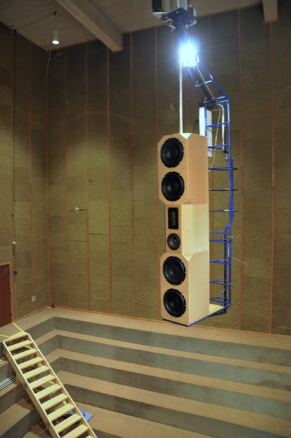
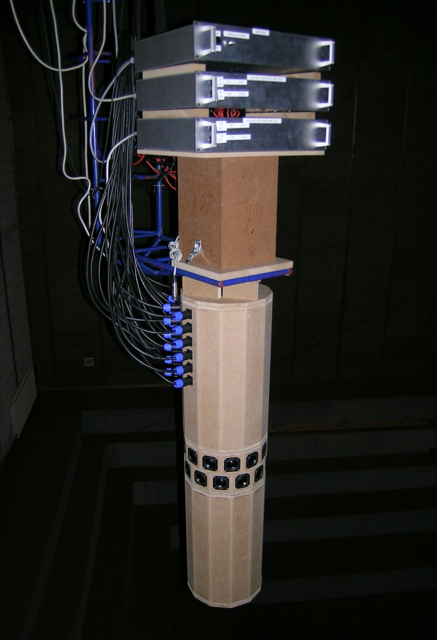
By early 2011, these loudspeakers were built (although not finished…) and ready for measurements and tuning. The photo below shows the “raw” loudspeaker on the crane in the Cube going out to be measured.
Those loudspeakers lived in Listening Room 1 for about a year. We’re bring people in for a “special demonstration” of a loudspeaker behind the curtain. The general consensus was that the loudspeakers sounded great – but when the curtain was opened, many people started laughing due to the sheer size (and the ugliness of my design, apparently…) of the loudspeakers.
The second “stream” was an idea that was born from Gert Munch’s goal of building a loudspeaker with a smooth power response as well as a flat on-axis magnitude response. The experiment was based on a “normal” two-way loudspeaker that had an additional side-firing dipole on it. The basic idea was that the two-way loudspeaker could be equalised to deliver a flat on-axis response, and the dipole could be used to correct the power response without affecting the on-axis sound (since the on-axis direction is in the “null” of the dipole). For more details about this project, please read this post.
After the “shark fin” experiment, we knew that we wanted to head towards building a loudspeaker with some kind of active directivity control to allow us to determine the amount of energy we sent to the nearby walls. Two members of the Acoustics Department, Gert Munch and Jakob Dyreby, had been collaborating with two graduate students (both of whom started working at B&O after they graduated), Martin Møller and Martin Olsen on exactly this idea. They (with Finn Agerkvist, a professor at DTU) published a scientific paper in 2010 called “Circular Loudspeaker Arrays with Controllable Directivity”. In this paper they showed how a barrel of 24 small loudspeaker drivers (each with its own amplifier and individualised DSP) could be used to steer a beam of sound in any direction in the horizontal plane, with a controlled beam width. (That paper can be purchased from the Audio Engineering Society from here.)
The next step was to start combining these ideas (along with other, more developed technologies such as Thermal Compression Compensation and ABL) into a single loudspeaker. The first version of this was an attempt to reduce the barrel loudspeaker shown in Figure 6 to a reasonable number of loudspeaker drivers. The result is shown below in Figure 7.
This first prototype had a hexagonal arrangement of tweeters and midranges (6 of each) and a square arrangement of woofers. Each driver had its own DSP and amplification with customised filters to do the “usual” clean-up of magnitude response in addition to the beam steering much like what is described in the AES paper.
Unfortunately, this version was not a success. The basic problem when trying to do directivity control actively is that you need the loudspeaker drivers to be as close together as possible to have control of the beam width in their high-frequency band – but as far apart as possible to be able to control their low-frequency band. In the case of prototype 1, the drivers were simply too far apart to result in an acceptably constant directivity. (In other words, the beam width was different at different frequencies.) So, we had to try to get the drivers closer together.
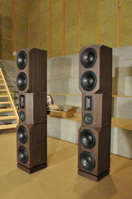
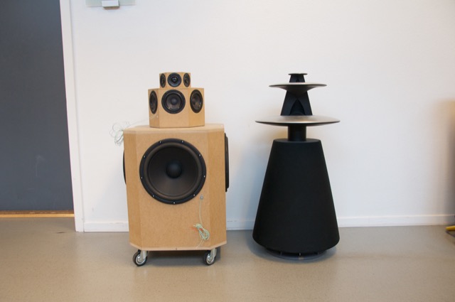
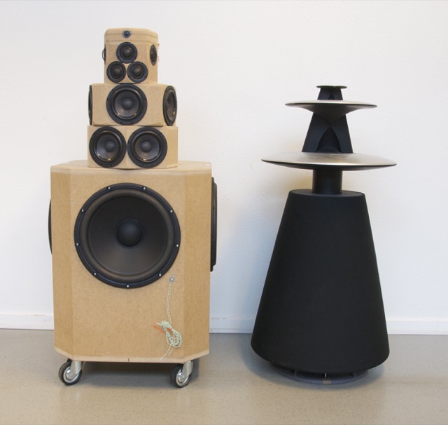
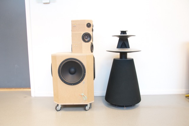
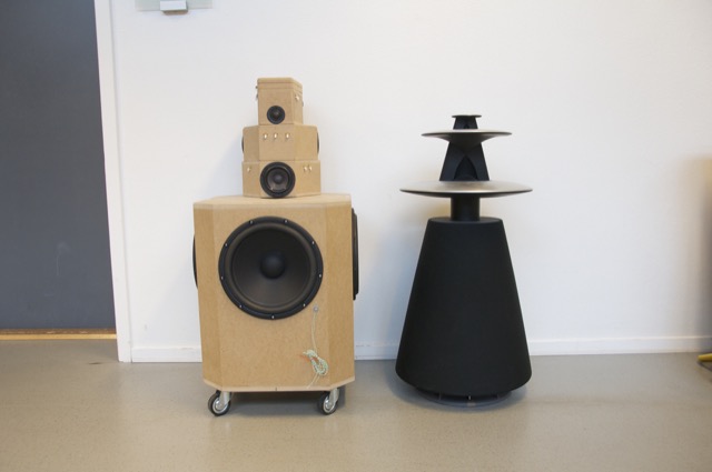
For the second prototype (shown below in Figure 8, 9, and 10) we decided to try to forget about a steerable beam – and just focus (forgive the pun) on a narrow beam with constant directivity (the same beam width at all frequencies). In addition to this, we experimented with a prototype 8mm supertweeter that would take care of the band from about 15 kHz and up.
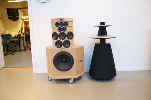
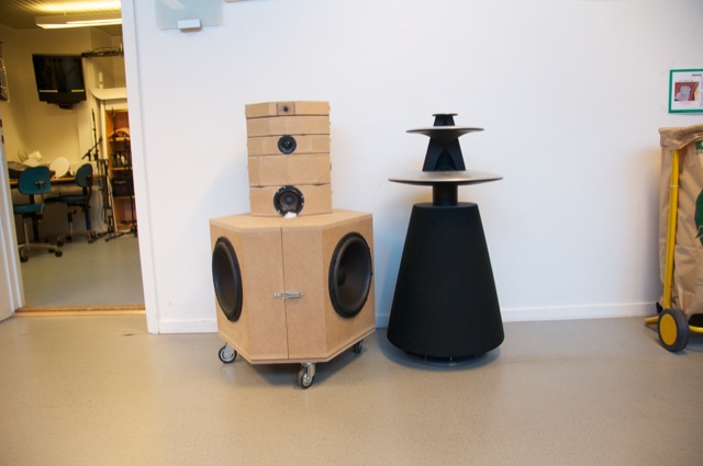
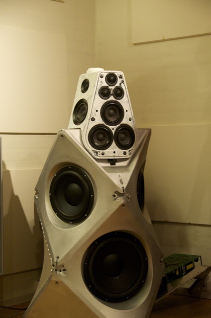
Although Prototype #2 sounded great in the sweet spot, it lacked the versatility of the first prototype. In other words, it was an amazing loudspeaker for a person with one chair and no friends – but it was not really a good loudspeaker for sharing… So, we started working on a third prototype that merged the two concepts – now called “Beam Width Control” and “Beam Direction Control”. The result in shown below in Figures 11, 12, and 13.
As you can see there, the “cluster” of 3 tweeters and 3 midranges comes from prototype 2 – but we re-gained side-firing drivers and rear-firing drivers to be able to steer the sound beam in either of 4 directions. The Beam Width could only be controlled for the front-firing beam, since it is a product of the cluster. You’ll also notice that the super tweeter was still there in this prototype. However, we also changed to a different tweeter and were starting to question whether the extra 8mm driver (and its amplifier, DAC and DSP path) would be necessary.
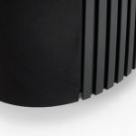
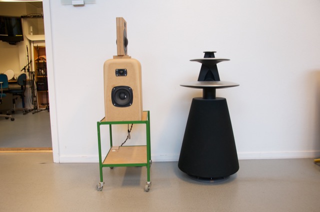
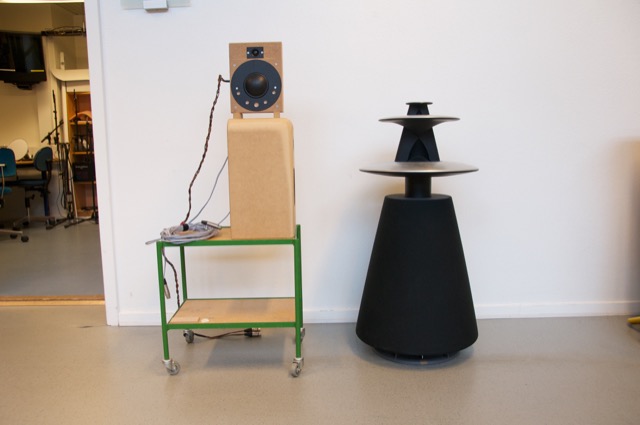
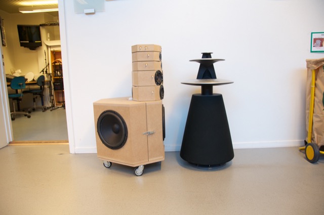
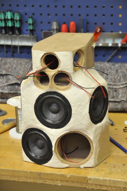
One thing that any good acoustical engineer knows is that corners cause diffraction. This is well-known at B&O as you can read here. Looking at the enclosure for the midranges and tweeters in the three previous figures, you can see many flat surfaces and corners – which, we assumed, were bad. So, we set about on an informal experiment to find out what would happen if we smoothed out the corners in an effort to reduce diffraction – or at least to change it. This was initially done by applying putty to the MDF enclosures and measuring the off-axis response of the result. One example of this (in progress of bring coated with putty – this was not the final version – it’s just there to show the process) is shown below in Figure 14.
Surprisingly, we found out in these tests that the “smoothing” of the structure around the midranges and tweeters either made no difference or made things worse. So, we continued on, knowing that the final result would be “smoother” anyway…
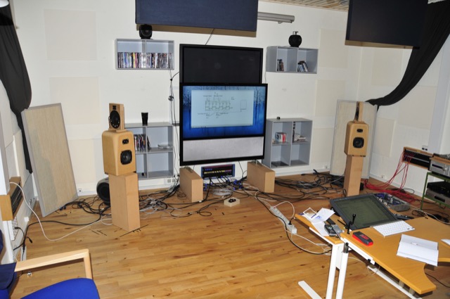
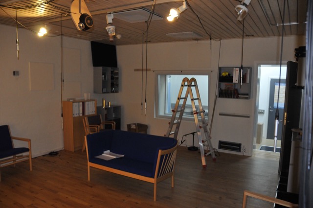
While that work was going on in the Cube, a third “stream” for the project was underway – the development of the Active Room Compensation algorithm. In the early versions, it was called “ASFC” or “Active Sound Field Control” – but as time went on and the algorithm evolved, we changed to a different system and gave it a different name. Photo 15, below, shows the listening room during one of the tests for the original algorithm. I count 9 microphones in there – but there may be more hiding somewhere.
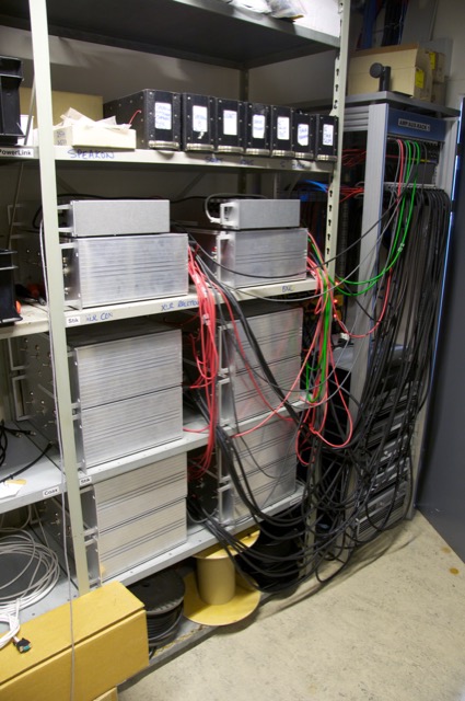
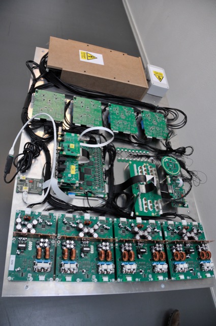
All of the prototypes shown above are just loudspeaker drivers in MDF enclosures. All of the DSP and amplification (in a worst-case, 17 channels in total per loudspeaker) were outside the loudspeakers. In addition, the amplifiers needed active cooling (a fancy way to say “fans”) so they had to be in a different room due to noise. The photo below shows the rack of DSP boxes (on top) and amplifiers (4 channels per box) used for the prototyping.
While this equipment was being used to evaluate and tune the complete prototypes, a parallel project was underway to find out whether we could customise the amplifiers to optimise their behaviour for the use. For example, if you know that an amplifier will only be used for a midrange driver, then it doesn’t need to behave the same as if it were being used for a full-range loudspeaker. I’ll describe that development procedure in a future blog posting, since it’s interesting enough to deserve its own story.
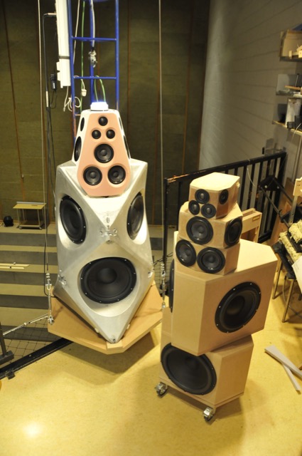
Finally, we were at a point where we built a first prototype of the “real thing”. This was hand-built using 3D-printed parts and a lot of time and effort by a lot of people. The first example of this stage is shown below on the crane in the Cube, sitting next to Prototype #4 for comparison. Notice that, by now, we had decided that the supertweeter was unnecessary, since the Scan-Speak tweeter we’re using was reliable up to at least 40 kHz. The only significant difference between the 4th prototype and the mechanical sample is that the wooden version has only one tweeter and one midrange pointing directly backwards. The “real thing” has two, aimed slightly towards the Left Back and Right Back. (See the Technical Sound Guide for more detailed information about this.)
Once the measurement of the first mechanical samples were done and the correct filters programmed into it, it was time to move a pair into the listening room to see (or, more importantly, to hear) if they performed the same as the wooden prototypes. The first setup of device numbers 2 and 3 (the first one stayed with the electronics team for testing) in Listening Room 1 in Struer is shown below in Figure 18. For reference, the room is 6 m deep x 5 m wide – and that’s a 55″ BeoVision 11 on the wall.
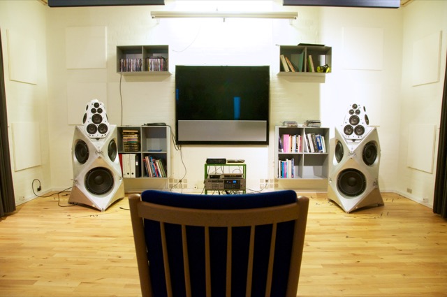
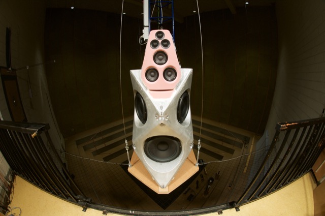
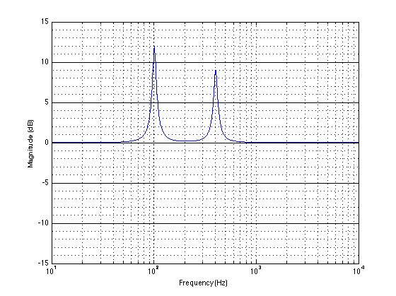
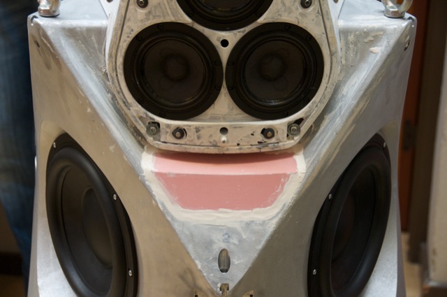
When we did the measurements on the samples shown in Figure 18 – both in the Cube and in the listening room, we could see that there was an unusual (and unexpected) dip in the on-axis magnitude response of about 1 dB at around 8o0 Hz. Unfortunately, it did’t seem to be easily correctable using filtering in the DSP, which meant that it was probably the result of a reflection somewhere off the loudspeaker, cancelling the direct sound at the listening position. After a day or two of playing with putty placed in various locations around the loudspeaker, we found that the problem was caused by a reflection off the “shelf” just below the face of the top unit. That can be seen in Figure 19, below.
The way to correct this problem was to bring the height of the shelf up, which also meant that it was closer to the face of the top cluster. (Note that the front panel is missing in Figures 19 and 20 – the actual face is the pink panel seen in Figure 22.) This fixed the problem, but it meant changing the mould for the aluminium enclosure. In the meantime, while that change was happening, we were able to 3D-print an insert of the same shape that could be used for the listening reference pair of loudspeakers. This meant that we didn’t have to wait for the new aluminium versions to start tuning.
Of course, the electronics team developed their components on a test bench, piece by piece. Eventually, all of those pieces came together into a single unit (minus the loudspeaker drivers and enclosures) which could be used for testing and software development. An example of one of those test boards (actually, the first one of its kind to be made – and one of the few with all of the amplifiers attached…) is shown below in Figure 21.
I’ll probably show some better photos of the DSP board in a later posting.
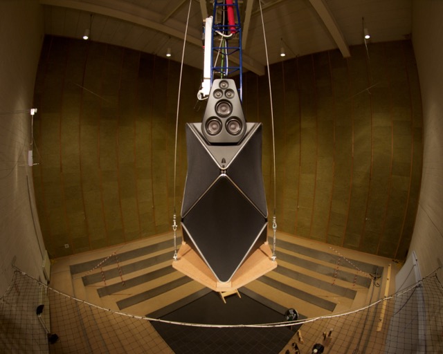
Finally, everything came together into a product that, acoustically and electrically, was identical to the production model. This is the version that we use for sound design. It’s shown (about to go out into the Cube for yet another round of measurements) in Figures 22 and 23, below.