After writing the previous posting, I couldn’t stop thinking about it. Mostly, I wanted to get a better idea of the shape of the waveform that results from the difference in a groove cut with a stylus and a spherically-tipped needle on a turntable pickup. To be perfectly honest, I’m not even interested in a ‘real’ simulation. I just wanted to get an intuitive idea of what’s happening down at that nearly-microscopic level. So, I used Matlab to draw some pictures.
Let’s take one period of a sine wave cut into the vinyl master with a chisel-shaped stylus:
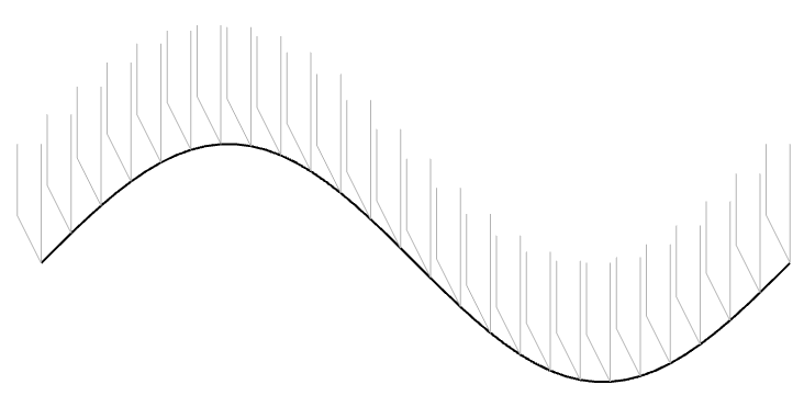
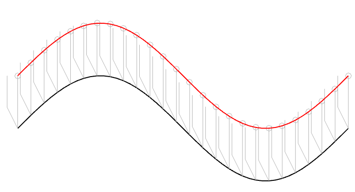
In theory, the pickup needle tracks this vertical movement exactly, as shown in Figure 2.
However, we already know that the pickup needle is NOT the same shape as the cutting stylus. In 1964, the needle would have had a spherical tip, which I’ve shown in Figure 3 as a series of semicircles (certainly NOT to scale…).
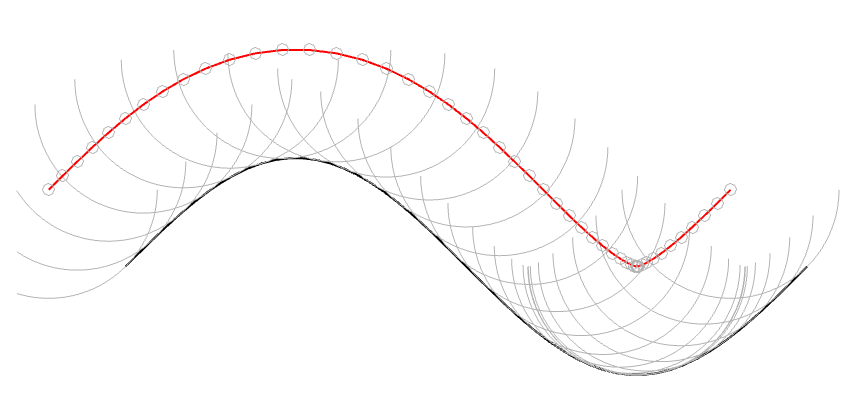
In Figure 3, I’ve connected the centres of the semicircles to make the red line. However, you may notice that this line is not directly above the black line because of the interaction between the slope of the original signal and the radius of the ‘sphere’ that I’m showing. This might be easier to see in Figure 4 which is the same as Figure 3, but I’ve ‘connected the dots’.
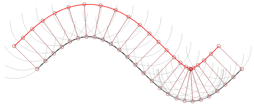
(1) One interesting thing about the figure above is that it shows that the point where the needle is resting on the vinyl surface isn’t always vertical – it’s 90º from the tangent of the groove wall (assuming a spherically-ground needle). This means that the output of the needle (which, we assume is determined only by its vertical movement) is actually sliding forwards and backwards in time on the recording, depending on whether the slope is positive or negative.
For example, if you look at the far left of Figure 4, you can see that the centre of the needle is to the left of the point where it’s touching the vinyl. If this is drawn so that the vinyl is moving from right to left (or the needle is moving from left to right – so it’s drawn from the perspective of someone looking in from the edge of the record) then this means that the output of the system is looking ahead in time.
When the needle drops back downwards, it’s delaying the signal, looking back in time.
If this were a digital system instead of an analogue one, we would be describing this as ‘signal-dependent jitter’, since it is a time modulation that is dependent on the slope of the signal. So, when someone complains about jitter as being one of the problems with digital audio, you can remind them that vinyl also suffers from the same basic problem…
(2) Another interesting thing is that, if we subtract the original signal on the vinyl’s surface from the actual path traced by the needle, we can see the tracing error itself. This is shown below as the red curve in Figure 5.
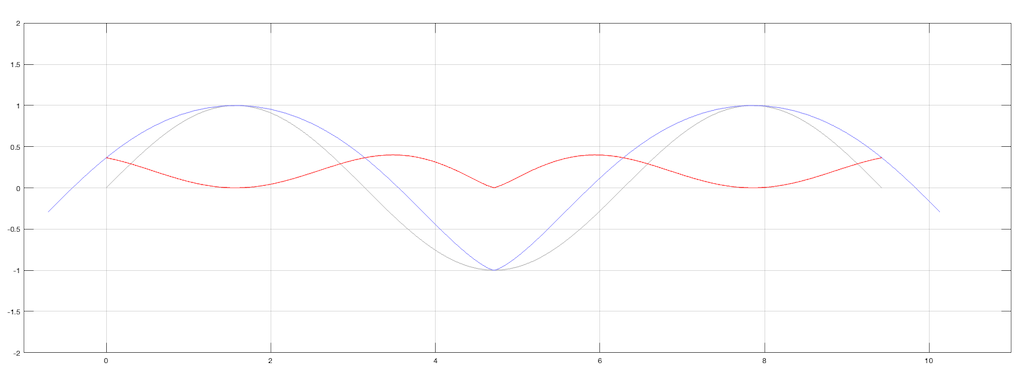
Notice that, although the original signal is symmetrical, the blue curve (the actual signal) is not. This means that it has a DC offset, which is easily seen in the error curve in red, which never drops below the vertical 0 line; the mean of the original signal.
(Remember, I’m exaggerating everything here just to get an intuitive understanding of what’s going on.)
Although I’ve done all of this analysis numerically using Matlab, I’ve also found a paper that describes this error analytically. It’s “Integrated Treatment of Tracing and Tracking Error” by Duane H. Cooper in the Journal of the Audio Engineering Society from January, 1964. In that paper, he shows the following drawing shown below in Figure 6. Compare the dotted line to the blue one above, for example. (It seems that I wasted my time doing math when I should have been reading old papers instead…)
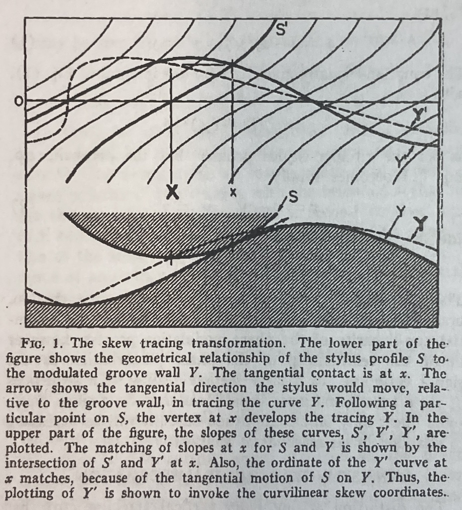
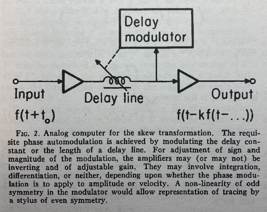
The horizontal distance in Figure 6 between the bold capital ‘X’ and the small ‘x’ is an angular rotation from the centre of the needle’s spherical tip and therefore a time shift in the playback of the recording. Later in the same paper, Cooper proposes an analogue computer that can predict this distortion by modulating a delay applied to the audio signal as a function of the signal itself. A representation of this from the paper is shown below in Figure 7. This prediction can then be used to generate the pre-emphasis distortion of RCA’s “Dynamic Styli Correlator”.
(3) The last thing that I’ve found is an extreme case that should never happen in real life, but it might. This is when the trough that the needle is dropping into is narrower than the diameter of the stylus. When this happens, the point where the stylus is touching jumps instantaneously from one side of the trough to the other. This is shown in Figure 8.
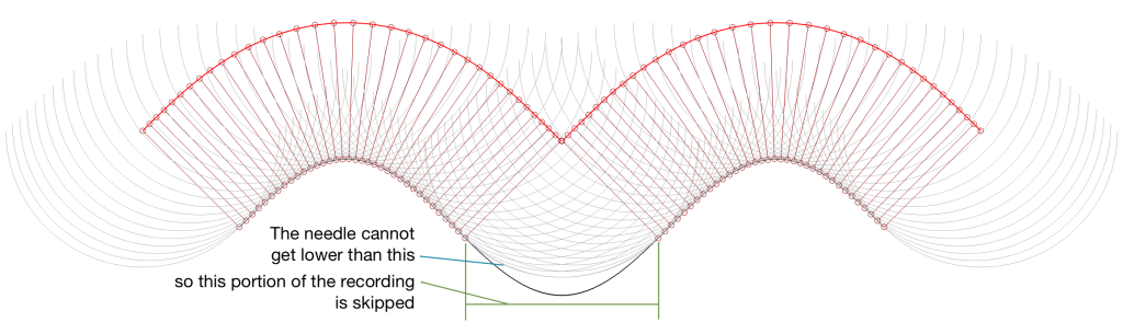
This is the same thing that happens when a tire of your car drops into a bad pothole. You roll off one edge of the hole, and hit the edge on the opposite side, but the part of the tire that is actually IN the pothole never actually touches the bottom.
This problem is the same as I described above; but instead of the output signal merely sliding in time, it’s jumping. One example I can think where this would happen in real life is when you play a CD-4 quad LP with a needle that isn’t made for it. However, in this case you won’t notice the problem, since the high-frequency FM modulated surround channels result in a more-or-less constant “ripple” on the groove wall. This means that your needle is just surfing along the tops of the ripples and never drops into a trough at all.